10
9 - PUSH TO OPEN INSTALLATION
9.1 - PIVOT ARM INSTALLATION - Location of Pivot Point
Measurements are taken from the center of pivot of the gate hinge.
The pivot arm needs to be securely mounted to the hinge post or equivalent mounting surface. It is recommended
to weld the pivot arm to a metal post. In order to achieve the correct articulation, geometry and rate of speed of the
gate it is critical that the measurements below are followed. The pivot arm may need to be cut to achieve the correct
placement of the actuator mounting hole. Measurements are taken from the center of pivot of the gate hinge.
Strip back 6” of black sleeve from connector end of the actuator cable.
Either cut and reverse the white and orange limit wires and the red and
black motor wires of the connector shown below or disconnect and
move the pins with the appropriate tool.
NOTE: Do not reverse battery wires
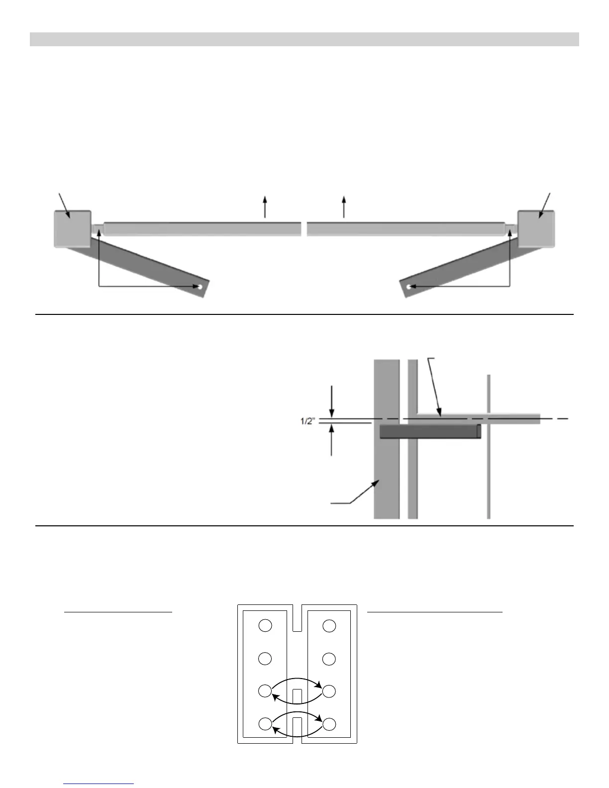
DIRECTION OF OPENING
GATES CLOSED
HINGE POST HINGE POST
LEFT HAND SWING RIGHT HAND SWING
TOP VIEW
6”
11”
6”
11”
The top edge of the Pivot Arm will be located
1/2” below the center line for the gate bracket.
The Pivot Arm must be level when secured.
Hinge Post
Center line of attachment point
for gate bracket
ORIGINAL PIN WIRING
1 ORANGE - Open Limit Input
2 WHITE - Close Limit Input
3 BLACK - Motor +
4 RED - Motor -
5 GREEN - Limit Switch Common
6 Not used
7 BLACK - Ground - Battery Negative
8 RED - Battery Positive (+12 VDC)
PUSH TO OPEN PIN WIRING
1 WHITE - Close Limit Input
2 ORANGE - Open Limit Input
3 RED - Motor +
4 BLACK - Motor -
5 GREEN - Limit Switch Common
6 Not used
7 BLACK - Ground - Battery Negative
8 RED - Battery Positive (+12 VDC)
7
5
3
1
8
6
4
2
9.3 - Wiring actuator(s) for push to open
9.2 Vertical position of pivot arm