14
16 - 635/636 CONTROL BOARD ADJUSTMENTS
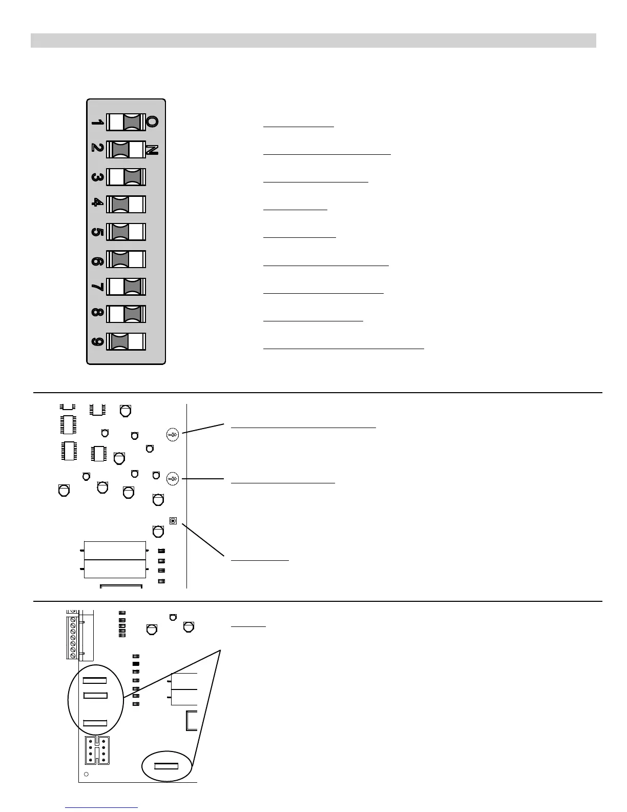
PROGRAM SWITCHES
Description
TIMER TO CLOSE - Automatically closes gate
ON - Close timer enabled OFF - Close timer disabled
CURRENT SENSITIVITY OPTION - Delays current sensing from start up
ON - 4 second delay OFF - 2 second delay
TIMER TO CLOSE OPTION
ON - timer to close works only when open limit switch is activated
OFF - timer to close works from any open gate position
SLAVE DISABLE
ON - disables slave side of dual board OFF - enables slave side of dual board
MASTER DISABLE
ON - disables master side of dual board OFF - Enables master side of dual board
MAXIMUM RUN TIMER OPTION
ON - stops and reverses gate if run timer times out before closing
OFF - stops gate if run timer times out before closing
MAXIMUM RUN TIMER VALUE
ON - 40 seconds OFF -20 seconds
TIMER TO CLOSE VALUE
ON - 20 to 70 seconds (adjustable) OFF - 10 to 35 seconds (adjustable)
OPEN, STOP, CLOSE CONTROL ENABLE
ON - allows for open, stop, close unit (optional) to operate gate
OFF - normal operation
(If 9 is on, terminals 4 & 5 must be normally closed for proper operation.)
OFF ON
Factory Setting
#1 OFF
#2 OFF
#3 ON
#4 OFF
#5 OFF
#6 OFF
#7 ON
#8 ON
#9 OFF
Fuses
There are 4 standard automotive type fuses on the 635/636 circuit board.
The EMERGENCY BYPASS connection is protected by a 15 Amp fuse. This fuse is only
used when the harness is plugged into the emergency bypass connector.
The remaining three fuses (one for each of the 12 Volt outputs) are 3 amp and help to
protect the board from short circuits by accessories.
TIMER TO CLOSE ADJUSTMENT
Rotate clockwise to increase time before gate closes. Rotate counter clockwise to
decrease time before gate closes. If program switch #3 is on, the gate must activate
the open limit switch in order for the timer to close to operate.
CURRENT SENSITIVITY
Rotate clockwise to decrease sensitivity (more force). Rotate counter clockwise to
increase sensitivity (less force).
WARNING: The current sensitivity should be adjusted to prevent injury in the event of
someone being entrapped in the gate. This feature should be periodically tested to
assure proper operation. Refer to SAFETY PRECAUTIONS.
LED ENABLE
Enables LEDs for installation and troubleshooting (must be depressed to observe
LEDs)