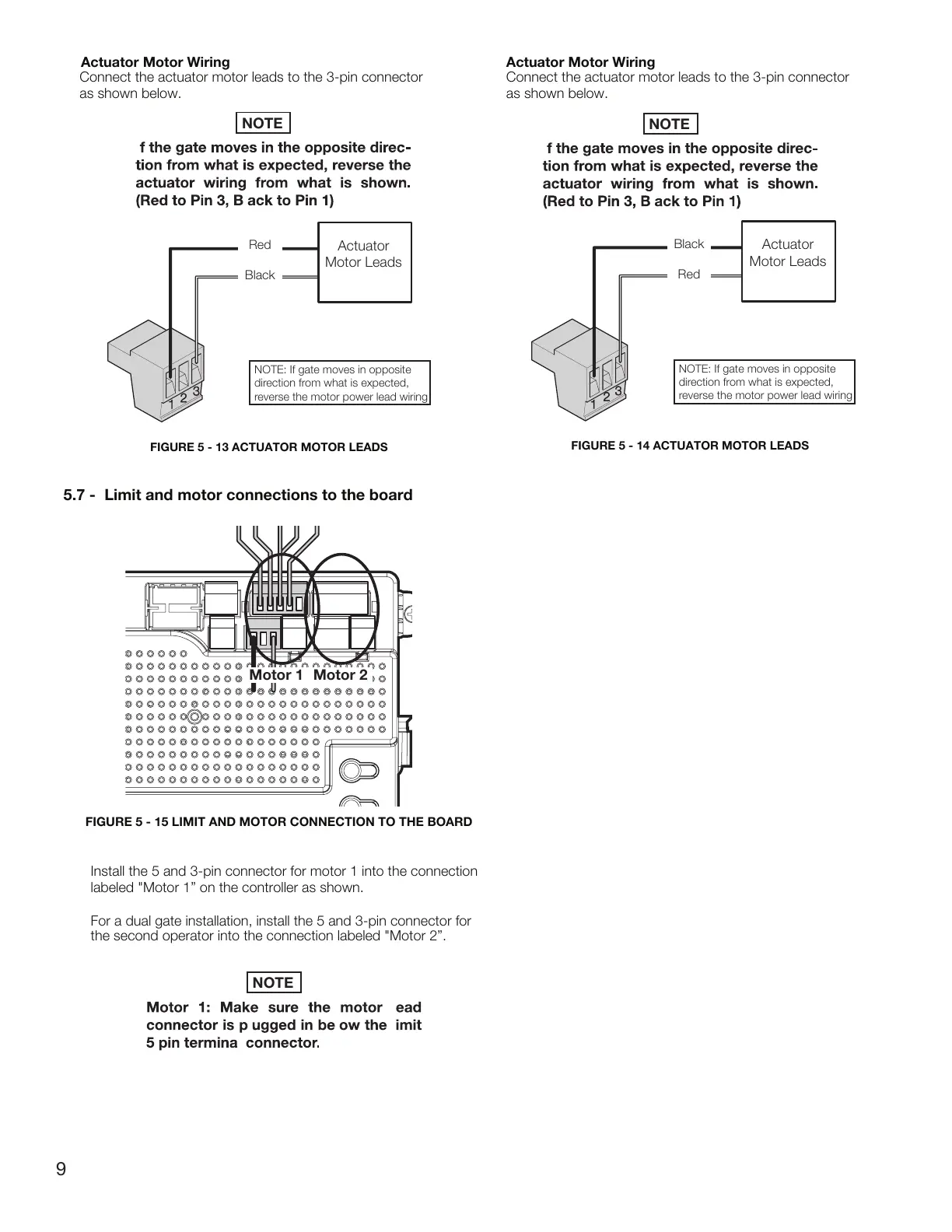
Actuator Motor Wiring
Actuator
Motor Leads
NOTE: If gate moves in opposite
direction from what is expected,
reverse the motor power lead wiring
Red
Black
Actuator Motor Wiring
Connect the actuator motor leads to the 3-pin connector
as shown below.
Connect the actuator motor leads to the 3-pin connector
as shown below.
Actuator
Motor Leads
NOTE: If gate moves in opposite
direction from what is expected,
reverse the motor power lead wiring
Black
Red
Motor 1 Motor 2
Install the 5 and 3-pin connector for motor 1 into the connection
labeled
"Motor 1” on the controller as shown.
For a dual gate installation, install the 5 and 3-pin connector for
the second operator into the connection labeled "
Motor 2”.
5.7 - Limit and motor connections to the board
FIGURE 5 - 13 ACTUATOR MOTOR LEADS
FIGURE 5 - 14 ACTUATOR MOTOR LEADS
FIGURE 5 - 15 LIMIT AND MOTOR CONNECTION TO THE BOARD
NOTE
NOTE
NOTE
9
1
2
2
1
3
3
 Loading...