MOTOR 1 LED - GREEN MOTOR 2 LED - GREEN
MOTOR 2 LED - RED
5.8 - Limit switch adjustment
FIGURE 5 - 19 LEARNING MODE - CLOSED LIMIT
10
MOTOR 1 LED - RED
FIGURE 5 - 18 LEARNING MODE - OPEN LIMIT
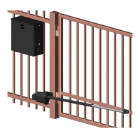
FIGURE 5 - 16 GATE BRACKET MOUNTING
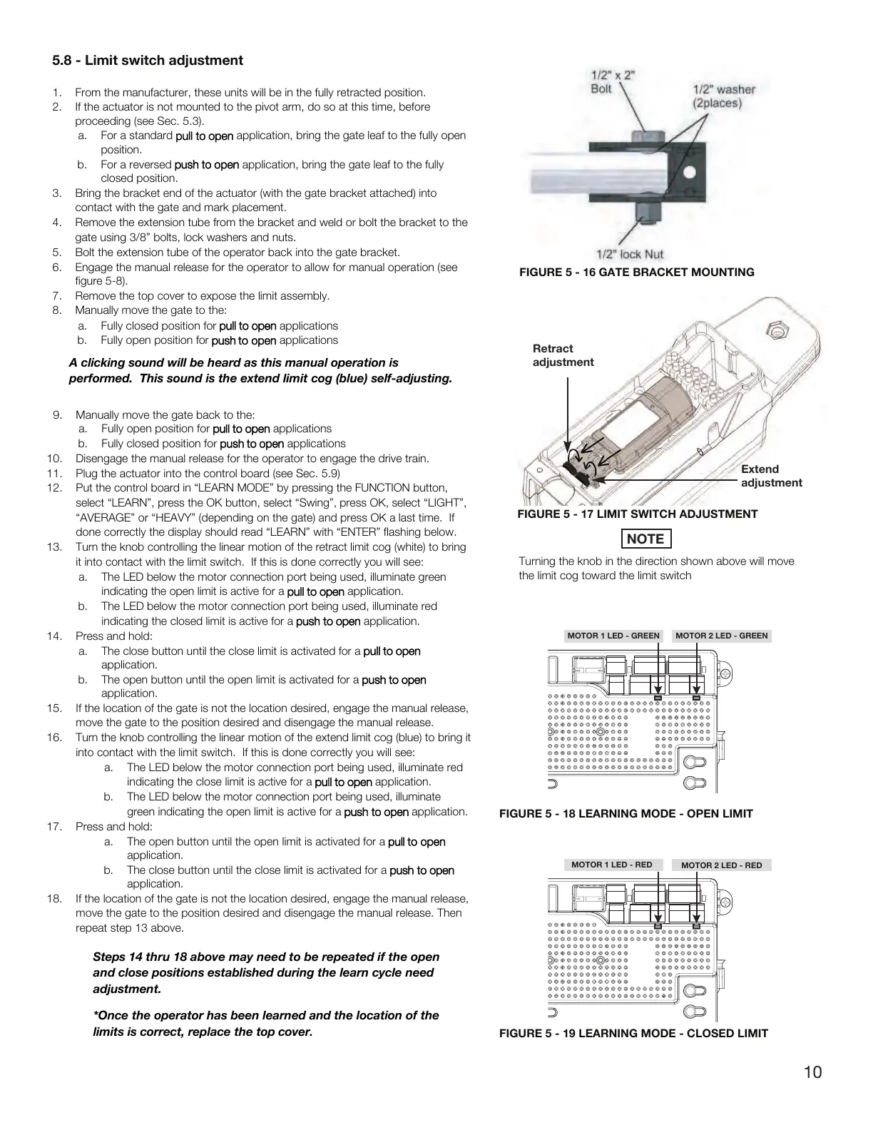
FIGURE 5 - 17 LIMIT SWITCH ADJUSTMENT
Retract
adjustment
Extend
adjustment
Turning the knob in the direction shown above will move
the limit cog toward the limit switch
NOTE
1. From the manufacturer, these
units will be in the fully retracted position.
2. If the actuator is not mounted to the pivot arm, do so at this time, before
proceeding (see Sec. 5.3).
a. For a standard
pull to open application, bring the gate leaf to the fully open
position.
b. For
a reversed
push to open application, bring the gate leaf to the fully
closed position.
3. Bring
the bracket end of the actuator (with the gate bracket attached) into
contact with the gate and mark placement.
4. Remove the extension tube from the bracket and weld or bolt the bracket to the
gate using 3/8” bolts
, lock washers and nuts.
5. B
olt
the extension tube of the operator back into the gate bracket.
6. Engage the manual release for the operator to allow for manual operation (see
figure 5-8).
7. Remove the top
cover to expose the limit
assembly.
8. Manually move the gate to the:
a. Fully closed position for
pull to open applications
b. Fully
open position for
push
to open applications
A clicking sound will be heard as this manual operation is
performed. This sound is the extend limit cog (blue) self-adjusting.
9. Manually move the gate back to the:
a. Fully open position for
pull to open applications
b. Fully
closed position for
push to open applications
10. Disengage the manual
release for the operator to engage the drive train.
11. Plug the actuator into the control board (see Sec. 5.9)
12. Put the control board in “LEARN MODE” by pressing the FUNCTION b
utton,
select “LEARN”, press the
OK button, select “Swing”, press OK, select “LIGHT”,
“AVERAGE” or “HEAVY” (depending
on
the gate) and press OK a last time.
If
done correctly the display should read “LEARN” with “ENTER” flashing
below.
13. Turn the knob controlling the linear motion of the
retract limit cog (white) to bring
it into contact with the
limit switch. If this is done correctly you will see:
a. The LED below the motor connection port being used, illuminate green
indicating the open limit
is active for a
pull to open application.
b. The LED
below the motor connection port being used, illuminate red
indicating the closed limit is active for a push to
o
pen application.
14. Press and hold:
a. The
close button until the close limit is activated for a
pull to open
application.
b. The
open button until the open limit is activated for a
push to open
application.
15. If t
he location of the gate is not the location desired, engage the manual release,
move the gate to the position
desired and disengage the manual release.
16. Turn the knob controlling the linear motion of
the extend limit cog (blue) to bring it
into contact with the
limit switch. If this is done correctly you will see:
a. The LED below the motor connection port being used, illuminate red
indicating the close limit is active for a
pull to open application.
b. The
LED below the motor connection port being used, illuminate
green indicating the open limit
is active for a push to o
pen application.
17. Press and hold:
a. The open
button until the open limit is activated for a
pull to open
application.
b. The close button
until the close limit is activated for a push to o
pen
application.
18. If
the location of the gate is not the location desired, engage the manual release,
move the gate to the position
desired and disengage the manual release. Then
repeat step 13 above.
Steps 14 thru 18 above may need to be repeated if the open
and
close positions established during the learn cycle need
adjustment.
*Once the operator has been learned and the location of the
limits is correct, replace the top cover
.
 Loading...