5
5 - INSTALLATION PROCEDURES
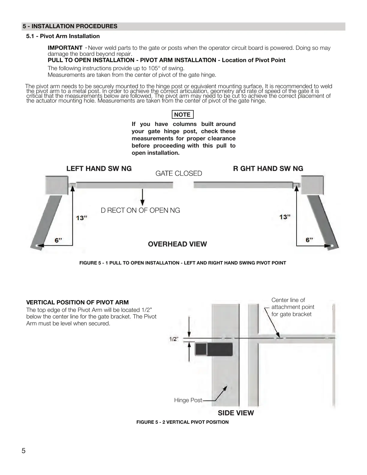
OVERHEAD VIEW
FIGURE 5 - 1 PULL TO OPEN INSTALLATION - LEFT AND RIGHT HAND SWING PIVOT POINT
FIGURE 5 - 2 VERTICAL PIVOT POSITION
V
ERTICAL POSITION OF PIVOT ARM
SIDE VIEW
The top edge of the Pivot Arm will be located 1/2”
below the center line for the gate bracket. The Pivot
Arm must be level when secured.
NOTE
If
you have columns built around
your gate hinge post, check these
measurements for proper clearance
before proceeding with this pull to
open installation.
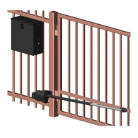
5.1 - Pivot Arm Installation
IMPORT
ANT
-
Never weld parts to the gate or posts when the operator circuit board is powered. Doing so may
damage the board beyond repair.
PULL TO OPEN INSTALLATION - PIVOT ARM INSTALLATION - Location of Pivot Point
The following instructions provide up to 105° of swing.
Measurements are taken from the center of pivot of the gate hinge.
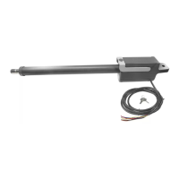
The pivot arm needs to be securely mounted to the hinge post or equivalent mounting surface. It is recommended to weld
the pivot arm to a metal post. In order to achieve the correct articulation, geometry and rate of speed of the gate it is
critical that the measurements below are followed. The pivot arm may need to be cut to achieve the correct placement of
the actuator mounting hole. Measurements are taken from the center of pivot of the gate hinge.
Center line of
attachment point
for gate bracket
Hinge Post
 Loading...