CBOX1050
Installation and Programming Manual
1717
MX4682 Rev. D ©2021
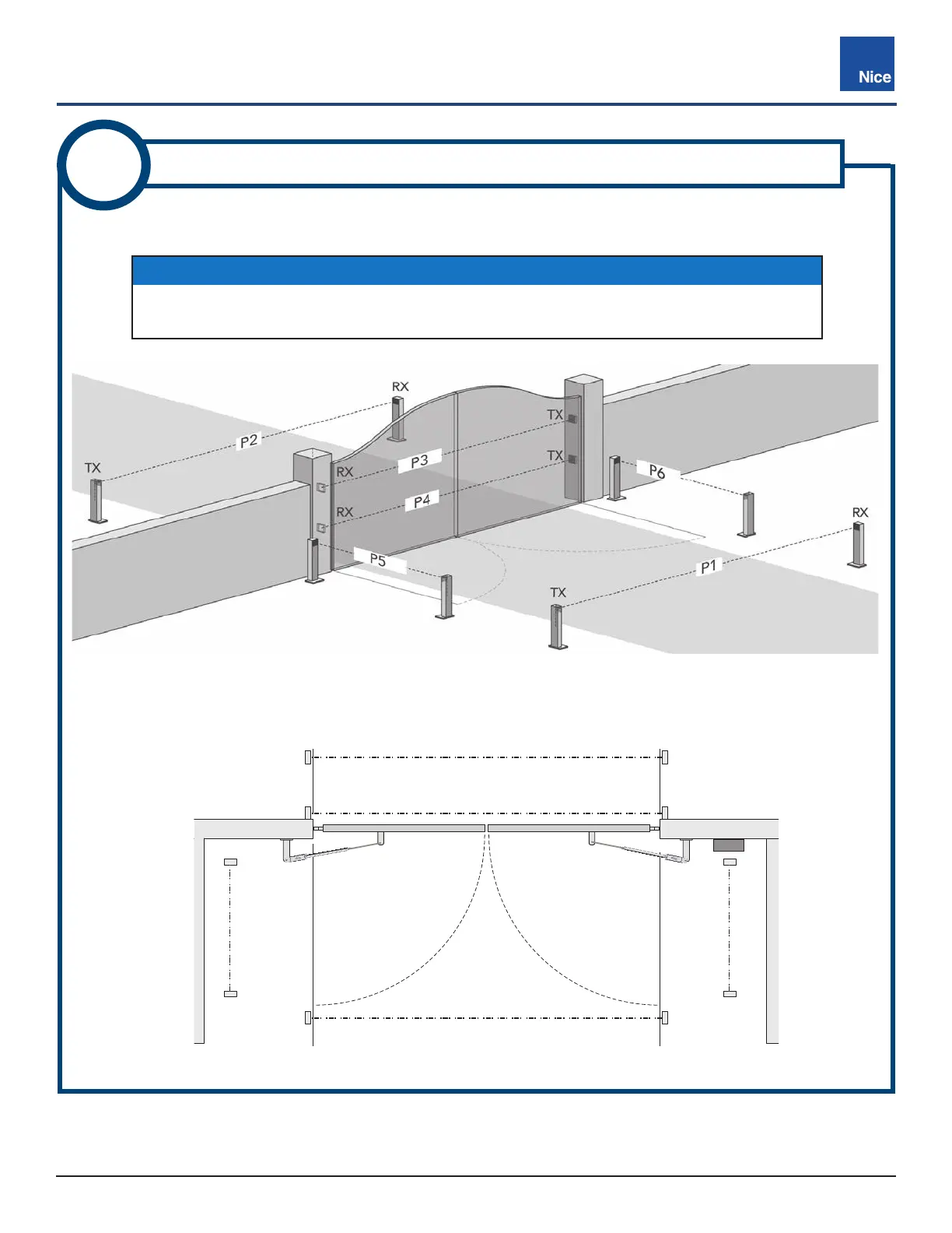
See below for suggestions of photo eye positioning for your gate configuration.
IMAGE 3-2: POSSIBLE ENTRAPMENT ZONES AND PHOTO EYE LOCATIONS (TOP VIEW)
IMAGE 3-1: POSSIBLE ENTRAPMENT ZONES AND PHOTO EYE LOCATIONS
RX = Receiver
TX = Transmitter
P* = Jumper Setting
3
DETERMINE BLUEBUS PHOTO EYE LOCATIONS
P6
(Open
Direction)
P5
(Open
Direction)
P3 and P4 (Close Direction)
P2 (Close Direction)
P1 (Close Direction)
TOP VIEW
NOTICE
Name designations in IMAGE 3-1 (P1, P2, etc.) are arbitrary designations used to indicate
jumper settings for each photo eye location. See INSTRUCTION 4 for jumper settings.