CBOX1050
Installation and Programming Manual
3333
MX4682 Rev. D ©2021
OXIBD/A RECEIVER INSTALLATION AND USE (CONT.)
ASSIGNING A REMOTE CONTROL TO THE OXIBD/A RECEIVER
Procure a functioning two (or more) button Nice remote control (see image below) with a battery installed
and assign it to the
OXIBD/A receiver as follows:
1. Press and hold the program button on the top of the OXIBD/A receiver module (IMAGE 19-2, Left) until
the green LED lights up on the top of the receiver, then release the button.
2. Within 10 seconds, press and hold any key on the Nice remote control until the LED in the Nice receiver
blinks green 3 times, indicating that the remote control is programmed to control the receiver.
3. After the LED on the Nice receiver blinks green 3 times, another 10 second interval is started to program
another Nice remote control if desired.
4. Repeat step 3 to program the additional Nice remote control (transmitter). Step 3 may be repeated as
many times as necessary to program all available Nice remote controls.
5. Verify that the Nice remote control(s) can control the gate by pressing one or more buttons individually
on the remote control(s).
6. If remotes do not function properly, refer to the FUNCTION/Radio Ch. Menu in SECTION 8 to assign the
correct function to the radio channels.
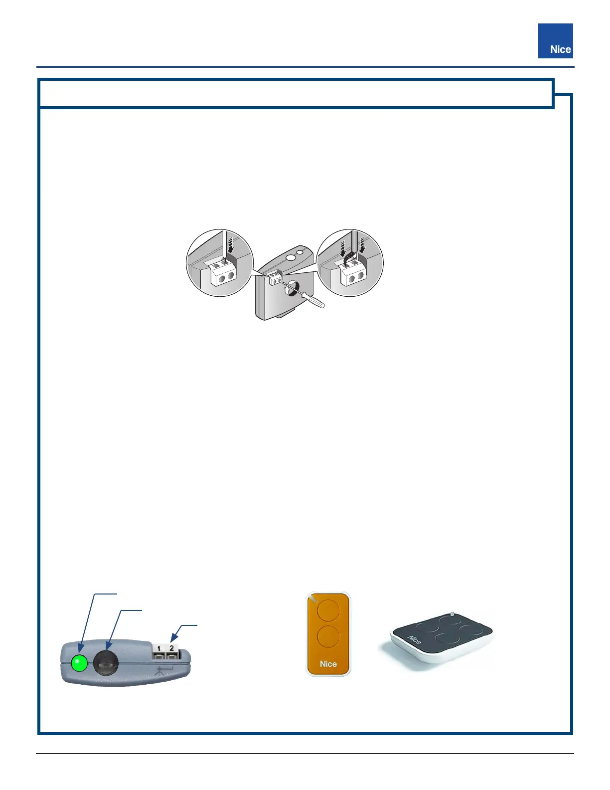
IMAGE 19-2: OXIBD/A RECEIVER (LEFT),
2-BUTTON REMOTE (MIDDLE) & 4-BUTTON REMOTE (RIGHT)
GREEN LED
ANTENNA
CONNECTOR
PROGRAM BUTTON
TOP VIEW
1 = Signal
2 = Shield
DETAIL BDETAIL A
1
2
INSTALLING AN ANTENNA TO THE OXIBD/A RECEIVER
Install a single wire or coaxial cable antenna to the OXIBD/A as follows:
1. Ensure power to the control board is OFF.
2. Connect supplied antenna wire to terminal 1 of receiver (DETAIL A, below).
3. If installing the external antenna from the kit (P/N ABF/A), connect the 50Ω impedance coaxial cable
directly to terminals 1 and 2 (DETAIL B, below). Lead = 1, Shield = 2.