the transmitter when channel 1 goes from OFF to ON and two brief activations when channel 1
goes from ON to OFF. This means that a visual or acoustic signal can be connected to channel 2 to
signal that the anti-theft device is connected or disconnected.
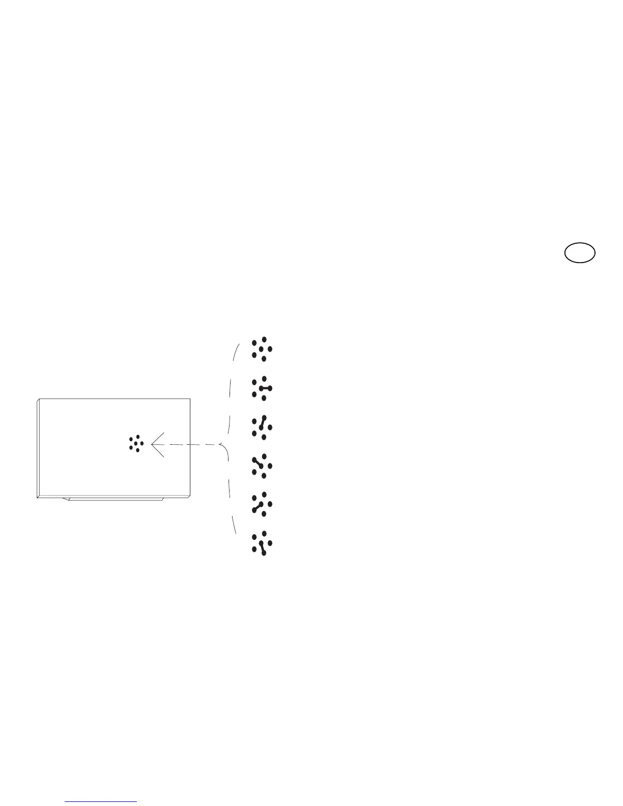
The special functions must be activated by means of a small spot of solder (Fig. 9) according to the
following table:
No jumper:
all temporary channels
Jumper 1:
1 step-by-step... 2,3,4 temporary
Jumper 2:
1,2 step-by-step... 3,4 temporary
Jumper 3:
1 timer... 2,3,4 temporary
Jumper 4:
1+2 anti-theft... 3,4 temporary
Jumper 5:
all step-by-step channels
GB
No jumper
Jumper 1
Jumper 2
Jumper 3
Jumper 4
Jumper 5