ENGLISH – 19
Table 12
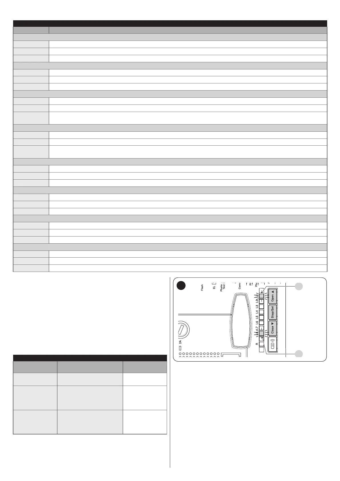
SIGNALS OF THE LED ON THE CONTROL UNIT BUTTONS
Status Meaning
L1 LED
OFF
During normal operation, it signals that the “Automatic closing” mode is not active
On
During normal operation, it signals that the “Automatic closing” mode is active
Flashes
Function programming in progress
L2 LED
OFF
During normal operation, it signals that the “Close after photo” mode is not active
On
During normal operation, it signals that the “Close after photo” mode is active
Flashes
Function programming in progress
L3 LED
OFF
During normal operation, it signals that the “Always Close” mode is not active
On
During normal operation, it signals that the “Always Close” mode is active
Flashes
Function programming in progress. If it ashes together with LED L4, the position recognition phase must be carried out
(see the “Automatic limit switch search and “STOP” input acquisition” paragraph)
LED L4
OFF
During normal operation, it signals that the “Stand-by” mode is active
On
During normal operation, it signals that the “Phototest” mode is active
Flashes
Function programming in progress. If it ashes together with LED L3, the position recognition phase must be carried out
(see the “Automatic limit switch search and “STOP” input acquisition” paragraph)
LED L5
OFF
During normal operation, it signals the OGI output as OGI (open gate indicator)
On
During normal operation, it signals the OGI output as ELS (electric lock)
Flashes
Function programming in progress
LED L6
OFF
During normal operation it signals that the “Pre-ashing” mode is not active
On
During normal operation it signals that the “Pre-ashing” mode is active
Flashes
Function programming in progress
LED L7
OFF
During normal operation, it signals that the “Condominium” mode is not active
On
During normal operation, it signals that the “Condominium” mode is active
Flashes
Function programming in progress
LED L8
OFF
During normal operation, it signals that the “Light gates” mode is active
On
During normal operation, it signals that the “Heavy gates” mode is active
Flashes
Function programming in progress
7.3 MAINTENANCE NOTIFICATION
The control unit allows for notifying the user when to perform
maintenance on the automation. The signal is emitted once the
number of manoeuvres completed equals the value set for the
“Maintenance warning” adjustable parameter (see the “Table 8”
paragraph).
The maintenance request signal is emitted through the FLASH
warning light.
The FLASH warning light and the maintenance indicator emit the
signals indicated in “Table 13” based on the number of manoeu-
vres completed with respect to the set limit.
Table 13
MAINTENANCE SIGNALS
Number of ma-
noeuvres
Signal on “Flash”
Signal on mainte-
nance indicator
Below 80% of
the limit
Normal (0.5 s on, 0.5 s
off)
On for 2 s at the
start of opening
Between 81%
and 100% of the
limit
At the start of the
manoeuvre, it remains
lit for 2 s then continues
normally
Flashes
throughout the
manoeuvre
Over 100% of
the limit
At the start and end of
the manoeuvre, remains
lit for 2 s then continues
normally
Flashes always
7.4 ANOMALY LOG
The control unit can display any anomalies that have occurred
in the last 8 manoeuvres (for example, the interruption of a ma-
noeuvre due to the intervention of a photocell or sensitive edge).
L1
L8
27
To check the list of anomalies:
1. press and hold the [Stop/Set] button for roughly 3 sec-
onds
2. release the [Stop/Set] button when the “L1” LED starts
ashing
3. press and release the [Open
p
] or [Close
q
] button to
shift ashing of the LED to “L8” (“Anomaly list” parameter)
4. keep the [Stop/Set] button pressed down (it must be kept
pressed throughout phases 5 and 6)
5. wait roughly 3 seconds, after which LED “L1” – corre-
sponding to the outcome of the last manoeuvre – will light
up
6. press and hold the [Open
p
] or [Close
q
] button to se-
lect the desired manoeuvre: the corresponding LED will
emit the same number of ashes as those normally emit-
ted by the warning light after an anomaly (see “Table 10”)
7. release the [Stop/Set] button.