ENGLISH – 3
– Inspect the system frequently, in particular the cables,
springs and supports to detect any imbalances and
signs of wear or damage. Do not use the product if it
needs to be repaired or adjusted, because defective
installation or incorrect balancing of the automation can
lead to injuries.
– The packing materials of the product must be disposed
of in compliance with local regulations.
PRODUCT DESCRIPTION AND INTENDED USE
2
2 PRODUCT DESCRIPTION AND INTENDED USE
MC424L is an electronic control unit for the automation of swing gates MC424L can command 24 V WINGO, TOO, SFAB elec-
tro-mechanical actuators. it incorporates an amperometric device that veries the force of the motors connected to it. This system
allows for automatically detecting the limit switches, memorising the work times of each motor and detecting any obstacles during
normal gate movement. These characteristics simplify the installation considerably, as the leaf offsets and work times do not require
any adjusting.
The control unit is programmed in advance for the most frequently used functions and incorporates a radio receiver for the remote
controls. In addition, a straightforward procedure can be implemented to select more specic functions (see the “PROGRAM-
MING” chapter).
MC424L is equipped with an SM-type connector for slot-in radio receivers (see the “Connecting an SM-type radio receiver“
paragraph) and an IBT4N-type connector which, through the IBT4N interface, can be used to connect BusT4 devices, such as the
Oview programmer (see the “Connecting the IBT4N interface” paragraph).
The control unit is congured for being powered with PS124 back-up batteries which, in case of a power outage, function as an
emergency power supply (see the “Connecting the PS124 back-up battery” paragraph). Moreover, the MC424L is congured for
being connected to a Solemyo solar power kit (see the “Connecting the Solemyo system” paragraph).
a
Any use of the product other than the intended use described is not allowed!
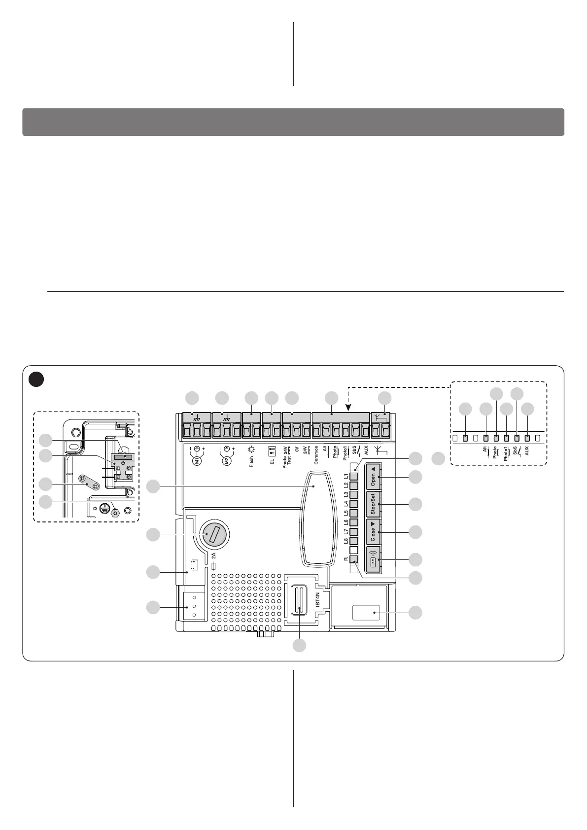
2.1 LIST OF CONTROL UNIT PARTS
The control unit is made up of an electronic command and control board housed and protected inside the box. “Figure 1” shows
the main parts making up the board.
M M 5 6 7 8 9 10 11 12 131 2 3 4
L9
OK
L10
L11
L12
L13
M M
L
N
A
B
C
D
R
S
U
T
E F G H I M N
O
L1
P1
P2
P3
P4
LR
L8
..
Q
1
A 24 V~ power supply connector
B Connector for PS124 back-up battery / Solemyo solar
power kit
C Service fuse (2 A, type F)
D “SM” connector for radio receiver
E M1 motor terminal (starts rst during the closing
phase)
F M2 motor terminal (starts rst during the opening
phase)
G Warning light terminal
H OGI output or electric lock terminal
I 24 VDC terminals for services and phototest
L9..L13 Input LEDs
OK “LED OK” status LED
L1..L8 Programming LED
LR Radio programming LED
M Input terminals
N Terminals for radio antenna
O Motor selector
Q Connector for IBT4N
R Mains fuse
S Mains power supply (L-Live; N-Neutral)
T Earth connection
U Cable clamp
P1..P3 Control unit programming buttons
P4 Radio programming button