TABLE 5 - First level functions
LED Function Description
L1 Automatic closure
L2 Reclose after photo
L3 Always close
L4 Stand by (Bluebus)
L5 Electric lock/Courtesy light
L6 Pre-flash
L7 “Close” becomes “Partial open 1”
L8 “Gate open light” or “Maintenance light”
Function ACTIVE: after an opening movement, there is a pause (equal to the programmed time) after which the control
unit automatic initiates a closure movement. The factory setting for the Pause time is 30 sec.
F
unction NOT ACTIVE: function is “semiautomatic” type.
Function ACTIVE
: if the photocells are activated during the opening or closing manoeuvre, the pause time is reduced to
5 seconds regardless of the programmed pause time.
With “automatic closure” disabled, if the photocells are activated during closure the “automatic closure” is activated with
the programmed “pause time”.
F
unction ACTIVE: in the event of a power failure, even of short duration, when power is restored the control unit detects
gate open and automatically starts a closure manoeuvre, preceded by 5 seconds of pre-flashing.
F
unction NOT ACTIVE: when power is restored the gate remains where it is
F
unction ACTIVE: 1 minute after the end of the manoeuvre, the control unit turns off the “Bluebus” output (connected
devices) and all the LEDs apart from the Bluebus LED which will flash more slowly. When the control unit receives a com-
mand normal operation is restored (with a short delay). This function has the purpose of reducing consumption, an impor-
tant aspect with battery or photovoltaic panel power supply.
F
unction ACTIVE: the “electric lock” output switches its operation to “courtesy light”.
F
unction NOT ACTIVE: the output operates as an electric lock.
F
unction ACTIVE: a 3 second pause can be added between the flashing light signal and the start of the manoeuvre to
provide advance warning of a hazard situation.
F
unction NOT ACTIVE: flashing light signal coincides with the start of the manoeuvre.
F
unction ACTIVE: all the commands corresponding to “Close” (“Close” input or “Close” radio control) are replaced by the
“Partial open 1” command.
F
unction ACTIVE: the “gate open light” output on the control unit switches to the “maintenance light” function.
F
unction NOT ACTIVE: the output operates as “gate open light”
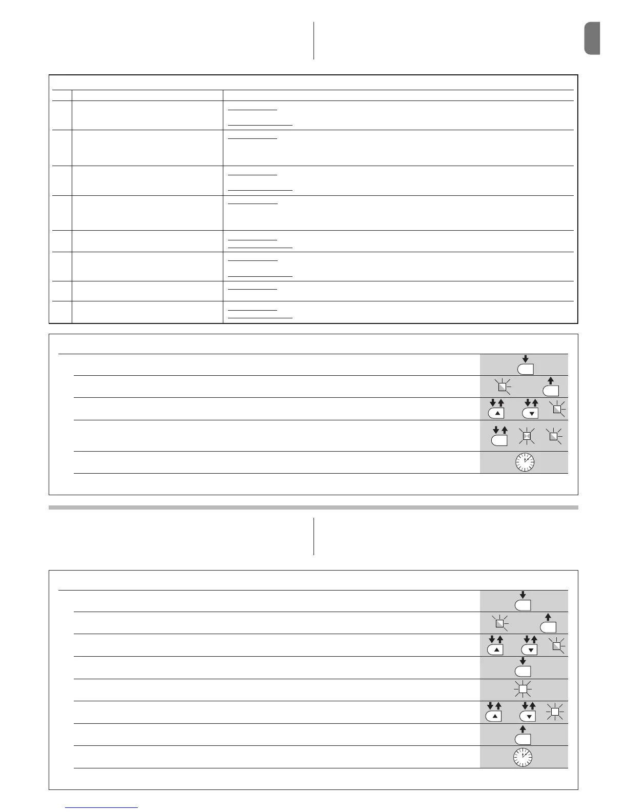
TABLE 6 – Programming procedure (first level functions)
01. Press and hold down the “Set” key for approx. 3 seconds;
02. Release the key when LED “L1” starts flashing;
03. Press the “” or “” key to move the flashing LED to the LED representing the function to be modified;
04. Press “Set” to change the status of the function:
(short flash = OFF; long flash = ON);
05. Wait 10 seconds (maximum time) to exit the programming mode.
Note – During this procedure, points 03 and 04 need to be repeated when programming other functions to “ON” or “OFF” during the phase itself.
L1
o
3 s
10 s
5.2 - Level two programming (adjustable parameters)
All level 2 functions are set by default as highlighted in grey in Table 8, and may
be modified at any time as explained in Table 7.
The parameters can be set on a scale from 1 to 8. To check the value corre-
sponding to each LED see Table 8. IMPORTANT – In the programming proce-
dure, the maximum time interval that can elapse between activation of one key
and the next is 10 seconds. When this time elapses, the procedure terminates
automatically, memorising the modifications made up until then.o.
5.1 - Level one programming (ON-OFF functions)
All level 1 functions are set by default to “OFF” and may be modified at any
time. To check the functions see Table 5. For the programming procedure see
Table 6.
IMPORTANT – In the programming procedure, the maximum time interval that
can elapse between activation of one key and the next is 10 seconds. When
this time elapses, the procedure terminates automatically, memorising the
modifications made up until then.
TABLE 7 – Programming procedure (second level functions)
01. Press and hold down the “Set” key for approx. 3 seconds.;
02. Release the key when LED “L1” starts flashing;
03. Press the “” or “” key to move the flashing LED to the LED representing the “input LED” of the parameter to be modified;
04. Press and hold the “Set” key through to completion of point 06;
05. Wait approx. 3 seconds, until the LED representing the current level of the parameter to be modified illuminates;
06. Press keys “” or “” to move the LED representing the value of the parameter;
07. Release the “Set” key;
08. Wait 10 seconds (maximum time) to exit the programming mode.
Note – During this procedure, points 03 to 07 need to be repeated when programming other parameters during the phase itself.