15
GB
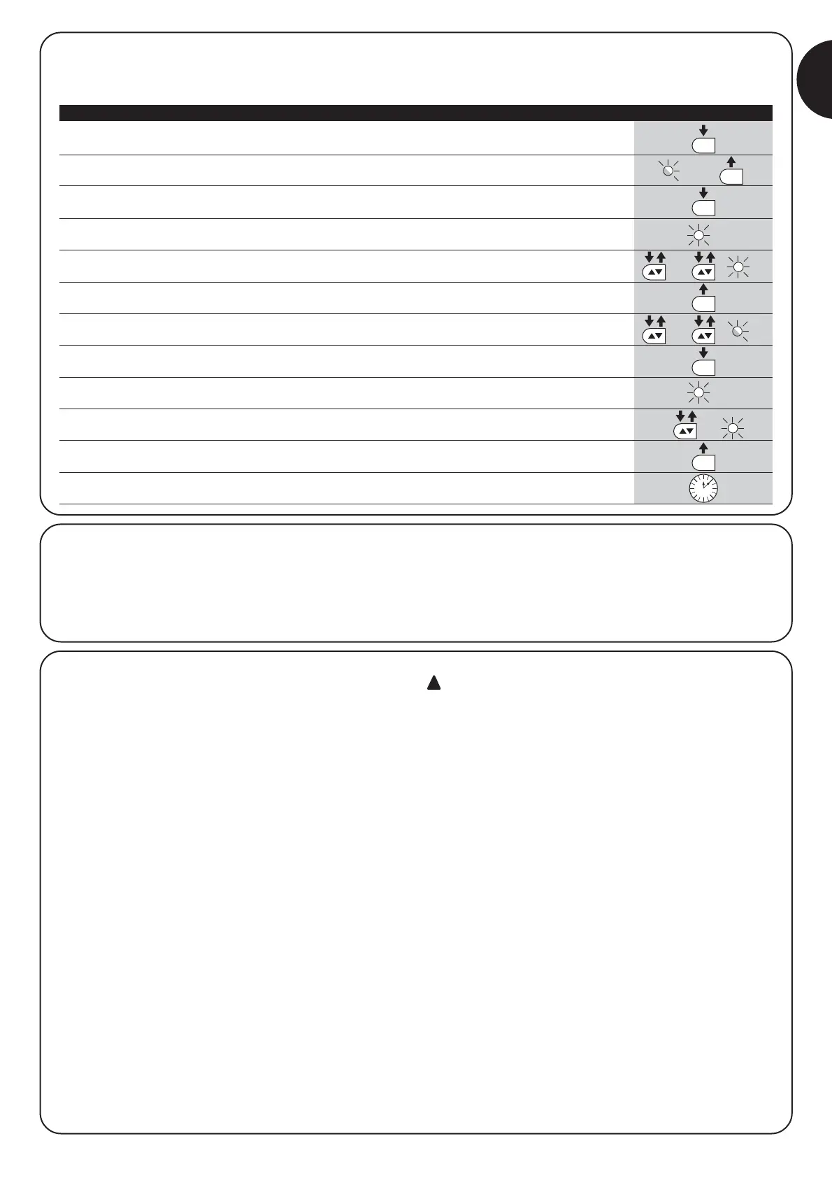
7.2.6) Level two programming example (adjustable parameters)
The sequence to follow in order to change the factory settings of the parameters adjusting the “Motor Force” on the average (input on L1
and L2 levels) increasing the “Pause Time” to 60 seconds (input on L3 and level on L3), and have been included as examples.).
1. Press the button [Set] and hold it down (approx. 3 s)
3s
2. Release the [Set] button when L1 LED starts flashing
L1
3. Press the button [Set] and hold it down during step 4 and 5
4. Wait approx. 3 seconds until LED L3, representing the current level of the “Motor Force” will light up.
L3 3s
5. Press the [▲▼] button twice to move the LED which is lit to LED L2, which represents the new
“Motor Force” value. L2
6. Release the button [Set]
7. Press the [▲▼] button twice to move the flashing LED to LED L3.
L3
8. Press the button [Set] and hold it down during step 9 and 10
9. Wait approx. 3 seconds until LED L2, representing the current level of the “Pause Time” will light up.
L2 3s
10. Press the [▲▼] button once to move the LED which is lit to LED L3, which represents the new
“Pause Time” value. L3
11. Release the button [Set]
12. Wait 10 seconds before leaving the programme to allow the maximum time to lapse.
10s
Table 18: Level two programming example Example
7.3) Adding or removing devices
Devices can be added to or removed from the ROAD200 automa-
tion system at any time. In particular, various devices types can be
connected to “STOP” input as explained in paragraphs “7.3.1 STOP
Input”.
7.3.1) STOP input
STOP is the input that causes the immediate interruption of the
manoeuvre (with a short reverse run). Devices with output featuring
normally open “NO” contacts and devices with normally closed “NC”
contacts, as well as devices with 8,2K1 constant resistance output,
like sensitive edges, can be connected to this input.
During the recognition stage the control unit recognizes the type of
device connected to the STOP input (see paragraph 4.3 “Recogni-
tion Length of the Leaf”); subsequently it commands a STOP when-
ever a change occurs in the recognized status.
Multiple devices, even of different type, can be connected to the
STOP input if suitable arrangements are made.
• Any number of NO devices can be connected to each other in par-
allel.
• Any number of NC devices can be connected to each other in
series.
• Several devices with 8.2K1 constant resistance output can be
connected “in cascade” with a single 8.2K1 termination resis-
tance.
• It is possible to combine Normally Open and Normally Closed by
making 2 contacts in parallel with the warning to place an 8.2K1
resistance in series with the Normally Closed contact (this also
makes it possible to combine 3 devices: Normally Open, Normally
Closed and 8.2K1).
if the STOP input is used to connect devices with safe-
ty functions, only the devices with 8,2K1 constant resis-
tance output guarantee the fail-safe category 3 according
to EN standard 954-1.