16
7.3.2) Photocells
The ROAD200 control unit is equipped with the “Phototest” function
which increases the reliability of the safety devices, making it possible
to achieve "category 2" in compliance with UNI EN 954-1 (edition
12/1998), in relation to the combination of control unit and safety pho-
tocells.
Every time a manoeuvre is activated the related safety device is con-
trolled and only if everything is correct is the manoeuvre started.
Whereas, if the test has a negative outcome (photocell blinded by the
sun, short circuited cable etc), the fault is identified and the manoeu-
vre is not performed.
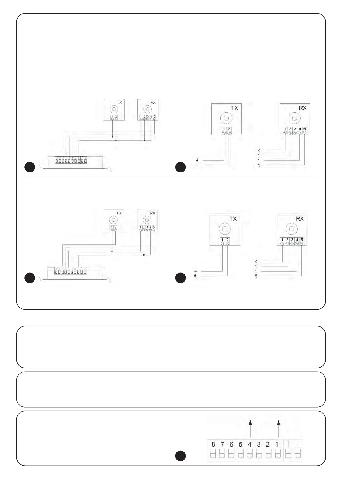
To add a pair of photocells, make the following connections.
• Connection without “Phototest” function (fig. 21 - 22):
Power the receiver directly from the control unit services output (terminals 1 - 4).
• Connection with “Phototest” function (fig. 23 - 24):
The photocell transmitter power supply is not taken directly from the services but through terminals 6-4 of the “Phototest” output. The max-
imum usable current on the “Phototest” output is 100 mA.
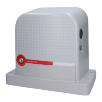
Activate the synchronism as described in the photocell instructions if 2 pairs of photocells are used that could interfere with one another.
7.4.1) “Always open” Function
The “Always open” function is a control unit feature which enables
the user to control an opening manoeuvre when the “Step-by-Step”
command lasts longer than 3 seconds. This is useful for connecting
a timer contact to the “Step-by-Step” terminal in order to keep the
gate open for a certain length of time, for example. This feature is
valid with any kind of “Step-by-Step” input programming. Please
refer to the “Step-by-Step Function” parameter in Table 15.
7.4) Special functions
7.4.2) “Move anyway” function
In the event that one of the safety devices is not functioning proper-
ly or is out of use, it is still possible to command and move the gate
in “Man present” mode. Please refer to the Paragraph “Control with
safety devices out of order” in the enclosure “Instructions and Warn-
ings for users of the ROAD gearmotor” for further information..
21 22
23 24
7.5) Connection of Other Devices
If the user needs to feed external devices such as a proximity read-
er for transponder cards or the illumination light of the key-operated
selector switch, it is possible to tap power as shown in Figure 25.
The power supply voltage is 24Vac -30% - +50% with a maximum
available current of 100mA.
24Vac
25