EN
English – 9
Note – Grey colour represents the factory setting.
WARNINGS:
- Do not set an excessively high value for the “motor force” as this may impair operation of the safety system or damage the pole;
- If the “Motor force control” is used in support of the system for impact force reduction, after each adjustment the force measurement procedure must be performed, as envisaged
by standard EN 12445.
- Wear and atmospheric conditions influence movement of the pole; motor force settings should be checked periodically.
L8 L1
L2
L3
L4
L5
L6
L7
L8
Manoeuvre 1 result (most recent)
Manoeuvre 2 result
Manoeuvre 3 result
Manoeuvre 4 result
Manoeuvre 5 result
Manoeuvre 6 result
Manoeuvre 7 result
Manoeuvre 8 result
The type of fault that has occurred in
the last 8 manoeuvres can be establi-
shed (see: paragraph 8.2 - malfunction
event log and Table 14).
A detailed log can be stored of all events
on SBAR (and other devices connected
on the network) by connecting the
Oview programmer
List of
faults
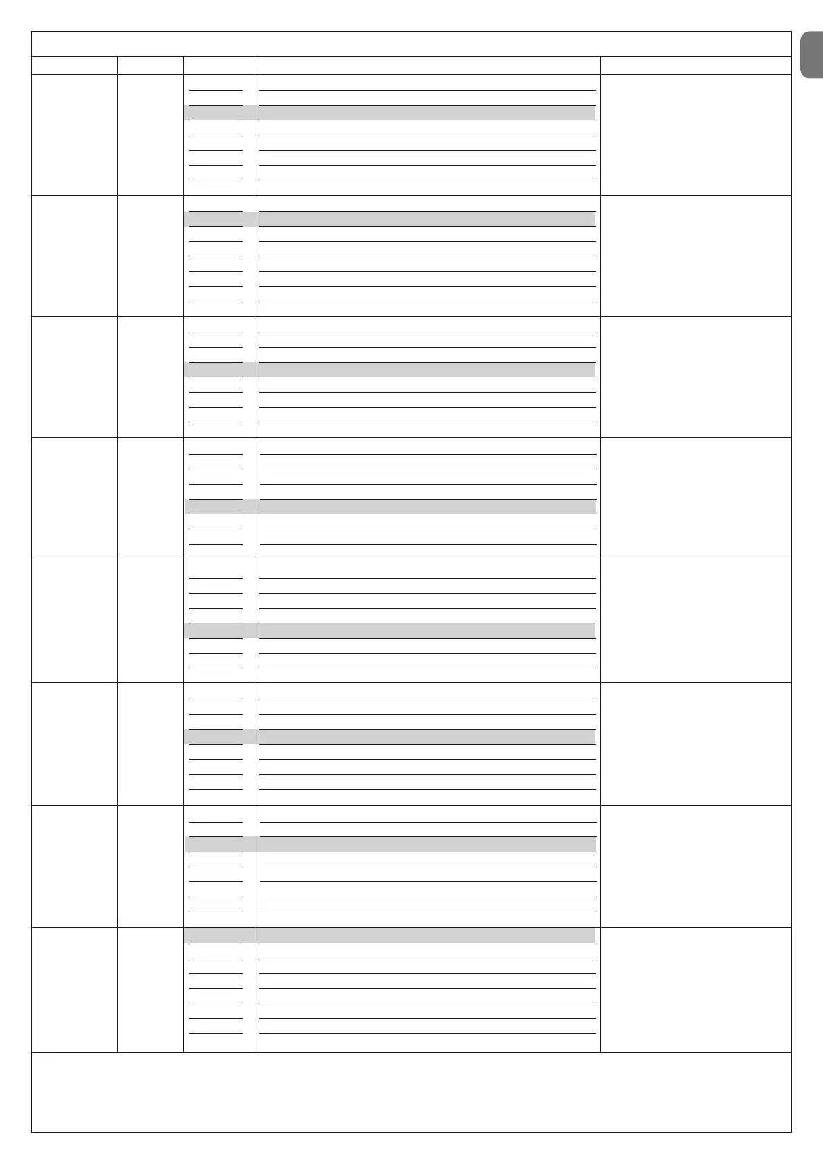
TABLE 7 - Second level functions
Input LED Parameter LED (level) Value Description
L1 L1
L2
L3
L4
L5
L6
L7
L8
5 seconds
10 seconds
20 seconds
40 seconds
60 seconds
80 seconds
120 seconds
200 seconds
Sets the pause time, i.e. the time that
passes between the end of an ope-
ning manoeuvre and the start of an
automatic closing manoeuvre
This parameter is only effective if the
“automatic Closure” is active.
Time
Pause
L2 L1
L2
L3
L4
L5
L6
L7
L8
Open – stop – close - stop
Open – stop – close - open
Open – close – open - close
Apartment block (more than 2 sec. generates Stop)
Apartment block 2 (less than 2 sec. generates partial opening).
Step by step 2
Hold-to-run
Opening in semi-automatic mode, closing in dead man mode
Sets the sequence of commands as-
sociated with the input or the radio
control: "Step by step”.
Function
Step by
step
L3 L1
L2
L3
L4
L5
L6
L7
L8
Speed 1 (30% - slow)
Speed 2 (47%)
Speed 3 (65%)
Speed 4 (82%)
Speed 5 (100%) - fast
Open V3, Close V2
Open V4, Close V3
Open V5, Close V4
Sets the motor speed during normal
travel.
Speed
Motor
L4 L1
L2
L3
L4
L5
L6
L7
L8
Pole Open Indicator Function (24 V - 10 W)
Active if pole closed (24 V - 10 W)
Active if pole open(24 V - 10 W)
Flashing light(12 V - 21 W)
Flashing light for pole lights (24 V - 10 W) - always flashes
Electric lock(24 V - 10 W)
Suction cup(24 V - 10 W)
Maintenance indicator (24 V - 10 W)
Selects the type of device connected
to the FLASH output.
Important! – If the programmed set-
ting is modified, check the type of vol-
tage of the new device connected to
the FLASH terminal and ensure that it
corresponds to the type of voltage of
the selected programming level.
Output
FLASH
L5 L1
L2
L3
L4
L5
L6
L7
L8
Force 1 (low)
Force 2
Force 3
Force 4
Force 5
Force 6
Force 7
Force 8 (high)
Adjusts the motor force control sy-
stem to adapt it to the weight of the
pole during the opening manoeuvre
and consequently the sensitivity of
obstacle detection.
Note – The force is acquired auto-
matically during execution of the first
two manoeuvres.
Motor force
on opening
L6 L1
L2
L3
L4
L5
L6
L7
L8
Force 1 (low)
Force 2
Force 3
Force 4
Force 5
Force 6
Force 7
Force 8 (high)
Adjusts the motor force control sy-
stem to adapt it to the weight of the
pole during the closing manoeuvre
and consequently the sensitivity of
obstacle detection.
Note – The force is acquired automa-
tically during execution of the first two
manoeuvres.
Motor force
on closure
L7 L1
L2
L3
L4
L5
L6
L7
L8
2500
5000
10000
15000
20000
30000
40000
50000
When the FLASH output is program-
med as a maintenance indicator: this
sets the maximum number of mano-
euvres to be performed, after which
the signal is sent to notify of the need
for automation maintenance.
Mainte-
nance
warning