EN
10 – English
Possible causes of malfunctions are listed below, which may occur during the
installation phase, or in the case of faults, possible remedies:
• The radio transmitter does not control the barrier and the transmitter led
does not illuminate: Check that the transmitter batteries are not discharged
and replace if necessary.
• The radio transmitter does not control the barrier but the transmitter led illu-
minates: check that the transmitter is correctly memorised on the radio receiv-
er. Ensure correct emission of the radio signal of the transmitter with the follow-
ing empirical test: Press a key and place the led against the aerial of a standard
radio switched on and tuned to FM at the frequency of 108.5Mhz or as close to
this value as possible; a slight noise with a scratching pulse noise should be
heard.
• No manoeuvre is performed when a command is sent, and the OK led
does not flash: check that the barrier is powered via the mains at 230 V. Also
check that the fuses F1 and F2 are not blown; in this case try to locate the
cause of the fault and then replace with a version with the same specifications;
see fig. 42.
• No manoeuvre is performed when a command is sent, and the flashing
light remains off: check that the command is effectively received; if the sent
command reaches the SS input, the OK led emits a double flash to indicate that
the command is received.
• The manoeuvre does not start and the courtesy light flashes a few ti -
mes: count the number of flashes and check with reference to the data in Table
9 in Chapter 8.
• The manoeuvre is performed, but shortly afterwards the pole blocks and per-
forms a brief inversion: the selected force value may be too low to enable
movement of the pole. Check correct balancing of the pole; if necessary set a
higher force value.
WHAT TO DO IF…
(troubleshooting guide)
7
8.1 - Total deletion of control unit memory
It is possible to delete all memorised data on the control unit and reset it to the
original factory settings:
01. Press and hold down “▲“ and “▼“ keys at the same time;
02. Release the keys when all Led illuminate (after approx.3 seconds);
03. When leds L1 and L2 start flashing, this means that the procedure is ter-
minated.
Important – This procedure does not delete
the parameter regarding the direc-
tion of motor rotation and the number of manoeuvres performed.
8.2 - Other functions
• “Always open” function
This function is a special feature of the control unit; it is associated with the
“Step Step” input and enables an “always
open” command when the Step Step
command remains active for more than 3 seconds. This function is valid for any
setting of the Step Step input (see “SS Function” in Table 7).
For example, it can be used to connect a clock for programming permanent
opening of the barrier during a specific time band.
• “Move anyway” function
If one or more safety devices malfunctions or is out of service, this function
enables control of the barrier in “hold-to-run” mode (for details, see chapter
“operation manual”).
• “Maintenance notification” function
This function enables notification of when an automation maintenance check is
necessary. The “Maintenance notification” parameter can be set with a value on
8 different levels (see Table 7).
The levels refer to the number of manoeuvres performed. The maintenance
notification is signalled via the Flash flashing light or by the maintenance indica-
tor according to the type of setting. The signals emitted by the Flash flashing
light and the maintenance indicator are shown in Table 9.
• Check of number of manoeuvres performed
The function “Maintenance notification” enables the user to check the number
of manoeuvres performed as a percentage of the maximum set limit. Proceed
as shown in Table 10.
• Manoeuvre counter reset
The manoeuvres can be reset at the end of the automation maintenance
phase. To proceed, see Table 11.
FURTHER DETAILS
8
TABLE 9
Number of manoeuvres Flash flashing light Maintenance indicator
Below 80% of the limit Normal (0.5 sec. lit - 0.5 sec. off) Light on for 2 seconds at the start of the
opening manoeuvre.
Between 81% and 100% of the limit Light on for 2 seconds at the start of the manoeuvre. Flashing for entire duration of manoeuvre then
continuing as normal
Over 100% of the limit At the start and end of the manoeuvre, remains lit Always flashes
for 2 sec., then continues as normal.
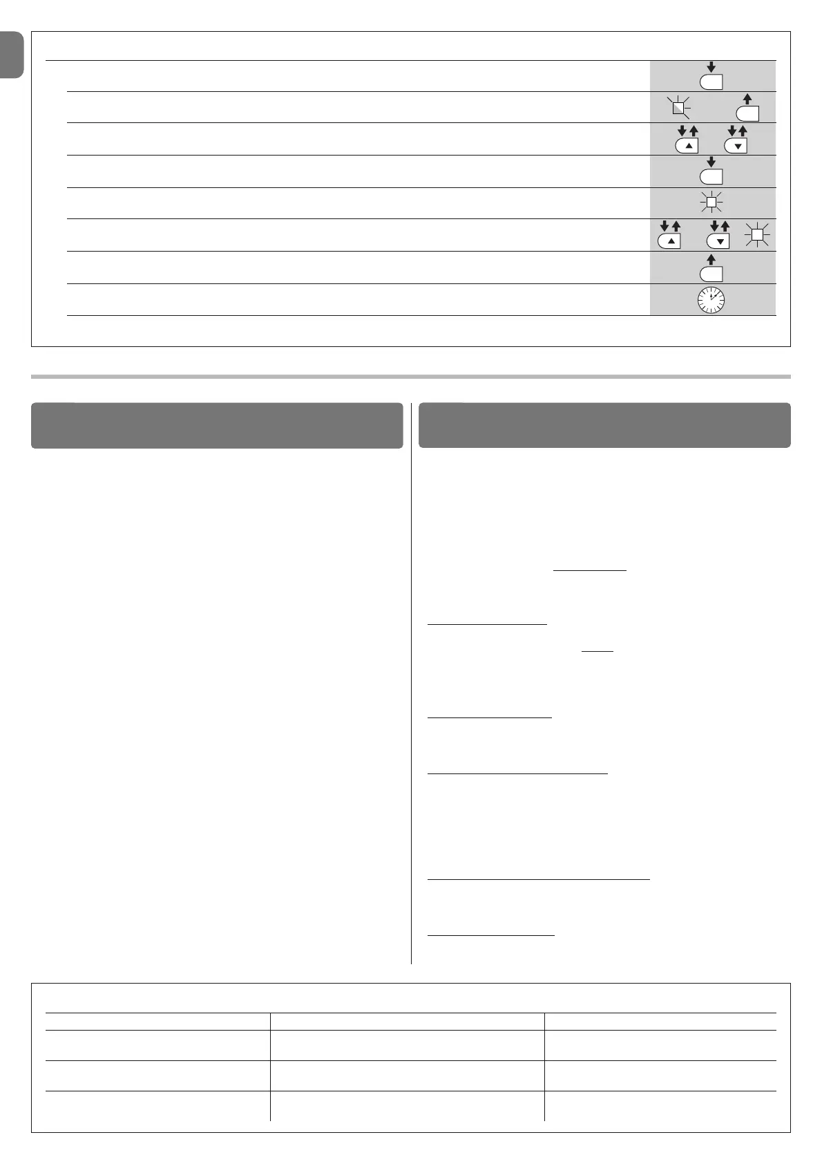
TABLE 8 - Programming procedure (second level functions)
01. Press and hold down the “Set” key for approx. 3 seconds;
02. Release the key when LED L1 starts flashing;
03. Press keys “▲” or “▼” to move from the flashing led to the led associated with the function to be modified;
04. Press and hold the “Set” key through to completion of point 06;
05. Wait approx. 3 seconds, until the LED representing the current level of the parameter to be modified illuminates;
06. Press keys ▲ or ▼ to move the LED representing the value of the parameter;
07. Release the “Set” key;
08. Wait 10 seconds (maximum time) to exit the programming mode.
Note – During this procedure, points 03 to 07 need to be repeated when programming other parameters during the phase itself.