4 – English
EN
CONTROL and CONNECTION ELEMENTS
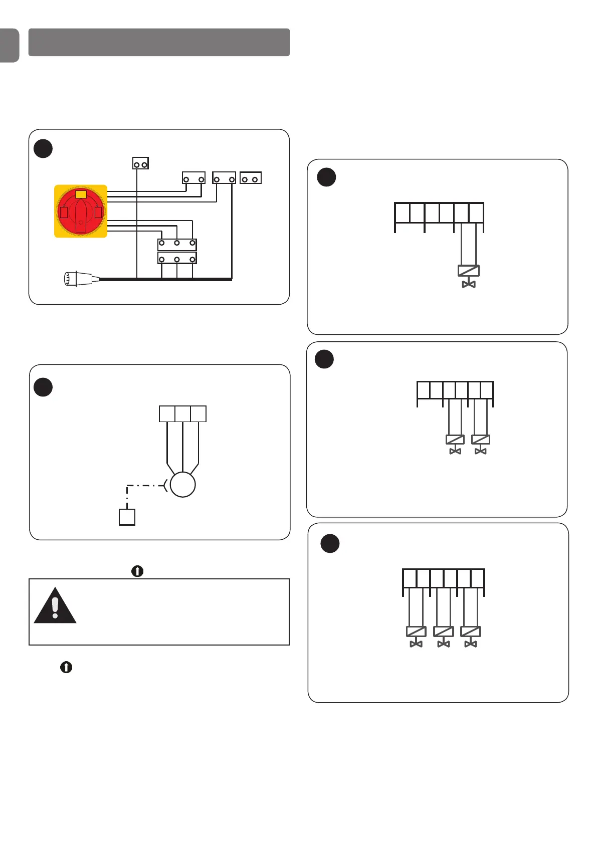
Network - UDL 2 connection - (fig. 1)
A 16A EEC plug is connected to terminals Y1a/L1,L2,L3, Y1c/N
and PE.
The network is to be connected to UDL 2 with a three-phase main
switch, as required by the EN 1398 standard.
Connection of the hydraulic motor (fig. 2)
The three-phase hydraulic motor is to be connected to the Y2
/U,V,W and PE terminals.
If the gearmotor is equipped with a neutral conductor, it is to be
connected to terminal Y1c/N*.
Direction of rotation control
Once the hydraulic motor is connected, check the direction of rotation
with the Ramp UP button .
If the ramp does not move after you have pressed the Ramp UP
button , reverse the direction of rotation of the hydraulic motor
next to terminal Y2.
Connection of the hydraulic valves (fig. 3-5)
Ramp with rotary side panel [P11/P12]
The ramp valve is to be connected to the Y4/5,6 (J12) screw
terminal.
Ramp with telescopic side panel [P21/P23/P24] (operation
with 2 valves)
The valve Lift ramp is to be connected to the Y4/5,6 (J12) screw
terminal and the valve Enable side panel is to be connected to the
Y4/3,4 (J13) screw terminal.
1
Y1c
PE
L2L1 L3
Y1b
Y1a
Power supply line EEC 16A
0
I
ON
0
OFF
L2L1 L3
L2L1
N
N
L3
L2
Input test
Main switch connection
Motor
U
V W
M
3~
PE
Y2
Hydraulic motor connection
2
Ramp with telescopic side panel [P31/P32/P33] (operation
with 3 valves)
The valve Lift ramp is to be connected to the Y4/5,6 (J12) screw
terminal, the valve Remove side panel is to be connected to the
Y4/3,4 (J13) screw terminal and the valve Side panel re-entry to the
Y4/1,2 (J14) terminal.
Test program [tSt]
In programming mode it is possible to control the corresponding
valve (1-3) or enable the ON/OFF motor function by pressing the
button on the cover.
Also see BASIC PROGRAMMING below.
3
Ramp
valve
Y4
1
J14
2 3
J13
4 5
J12
6
Valve - ramp connection
Enable
side panel
valve
Y4
1
J14
2 3
J13
4 5
J12
6
Lift
ramp
valve
Double valves connection
4
5
Y4
1
J14
2 3
J13
4 5
J12
6
Lift
ramp
valve
Extract
valve
Triple valves connection
Attention!
If optional switches (vehicle detector, wheel
wedge, protection barrier or door enabling) are
connected to the UDL2 control unit, they must
first be connected in the correct sequence!