EN
English – 3
The planning and production of the devices that form the UDL 2
control units for loading ramps, and the instructions contained in this
manual are perfectly compliant with the current safety standards.
Nevertheless, an incorrect installation can cause serious injury to the
persons that work on the plant or that use it. For this reason, during
installation it is important to follow all the instructions contained in
this manual.
Do not start installation if you have any doubts of any kind
and, if necessary, contact the Nice Assistance Service.
WORK IN SAFE CONDITIONS!
ATTENTION! – It is important to follow these instructions for
reasons of safety.
ATTENTION! – Strictly preserve the instructions safety
purposes with care.
Strictly follow the instructions below.
– Make only the electrical connections described in this
manual : incorrect wiring can cause serious damage to the
plant.
– In the case of use outdoors, the power supply cable supplied
must be totally protected with a special protection pipe.
In view of the risks associated with the installation and with
system control, it is necessary to install the product following
these instructions:
– Execute only the modifications described in these instructions.
Any other modification can cause serious mal functio ning. The
manufacturer declines all responsibility for any damages caused
by arbitrary modifications introduced to the devices.
– Do not position the devices near sources of heat or unprotected
flames. This can cause malfunctioning, fire and other dangers.
– During installation the devices should not be immersed in water or
other fluids. Prevent the infiltration of fluids into the devices.
– The packaging material must be disposed of in strict observance
of current regulations.
ATTENTION! – Preserve this manual with utmost care to make
device disposal or maintenance operations easier in the future.
Description and use
UDL 2 is a unit for controlling loading ramps with telescopic or rotary
side panel and for controlling a shelter for vehicles with additional
module. The control unit is set with the program appropriate for the
selected type of ramp. The programs are indicated in the manual
with the letter P followed by a number. More information is available
on request.
All the common safety elements can be connected.
With the application of a PEEP customisation module, other options
are possible.
To activate the ramp, simply press the corresponding button on the
control unit.
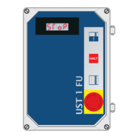
It is possible to control industrial doors, for example rolling shutters,
sectional doors and folding doors, in combination with UST1 /
UST1K door control unit.
Any other use is considered improper! The manufacturer
declines all responsibility whatsoever for damages caused
by improper use of the various system devices not compliant
with what is indicated in this manual.
The plant manufacturer is responsible for the complete plant. He
must fulfil the current regulations and directives (e.g. DIN 1986, EN
12050, EN 1398). He is responsible for drawing up the technical
documentation of the entire plant to be supplied together with the
plant.
It is mandatory to comply with the provisions and national and
local regulations regarding installation, accident prevention
and safety at the workplace.
It is recommended to disconnect the plant from the electrical
power supply during work on the ramp or door.
Checks before installation
Carefully read these assembly and use instructions before beginning
installation of the control unit.
The manufacturer declines all responsibility and obligation of
warranty if any arbitrary changes in construction are made without
previous written authorisation or installation not compliant with the
assembly instructions is executed.
The plant manufacturer must ensure that the EMC directives,
low voltage directives, machinery directives and directives on
construction products are observed.
ATTENTION!
The control unit cannot be used in areas at risk of explosion.
ATTENTION!
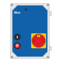
Connect the power supply cable to terminal Y1a (L1, L2, L3) Y1c (N)
and to the PE terminal of the base board.
The 3-pole main switch is connected to the Y1b and Y1c (L1, L2,
L3) terminals.
The power supply cable must be protected on-site with 3 x 16A
fuses.
The fuse must have a value such that the gearmotor makes the fuse
trip if it becomes blocked.
GENERAL RULES OF SAFETY
ENGLISH
KNOWLEDGE OF THE SYSTEM AND
PREPARATION FOR INSTALLATION