EN
English – 7
Now Lr0 appears on the display.
Lr is the ramp lowering time when the AUTORETURN button
is enabled in 00E status. The basic time set is 5 seconds. By
pressing the Ramp UP button repeatedly, now it is possible to
select a number between 1 and 9. Since every step is equal to 1
second, it is possible to set a value between 5 seconds (minimum)
and 14 seconds (maximum).
To confirm and store the selected time Lr press the AUTORETURN
button
.
Now rb0 appears on the display.
With the Ramp UP button , now it is possible to select a value
between rb0 and rb9 where rb0 = disabled door and rb1-rb9 =
enabled door (with a door operation time equal to the value set
multiplied by 5, e.g. 9x5 = 45 seconds).
Press the AUTORETURN button
again to store the setting.
Now Li0 appears on the display.
Li is the maximum return time of the side panel after resetting.
The basic time set is 3 seconds. By pressing the Ramp UP button
repeatedly, now it is possible to select a number between 1 and 9.
Since every step is equal to 2 seconds, it is possible to set a time
between 3 seconds (minimum) and 21 seconds (maximum). To confirm
and store the selected time Li the AUTORETURN button
.
Now Lc0 appears on the display.
Lc is the lifting time of the loading ramp in the 00C status.
Now it is possible to set the lifting time of the loading ramp in status
C. The basic time set is 3 seconds. By pressing the button
repeatedly, now it is possible to select a number between 1 and 9.
Since every step (number) corresponds to 1 second, it is possible
to select a time between 3 seconds (minimum) and 12 seconds
(maximum).
To confirm and store the selected time Lc presso the button
to confirm (to store).
Now
Ar0 = Autoreturn disabled
or
Ar1 = Autoreturn enabled appears on the display.
If the Shelter function (P08=1) is enabled on the
customisation module, now SA appears on the display.
0= automatic function disabled. To enable and disable the
shelter, use the Shelter Start button.
1 = the shelter must be enabled with the Shelter Start
button before opening of the door.
The shelter is automatically disabled with closing of the
door.
2 = the shelter is automatically enabled and disabled,
respectively, when the door is opened and closed.
PC 0-9
Sensitivity of the current measurement for reading the side panel of
the loading ramp in the opening position.
OPERATION WITH CUSTOMISATION MODULE
CUSTOMISATION MODULE [PEEP] CONNECTION
If the loading ramp is run with one of the
options described below, it is necessary to apply
a customisation module [PEEP] on the Y8 coupling.
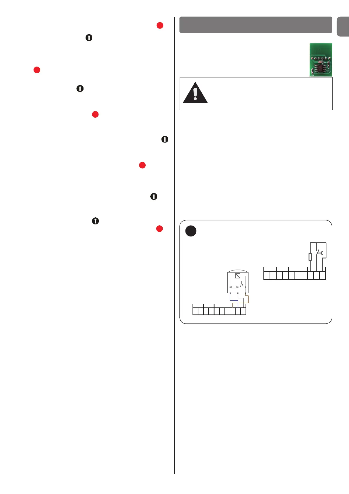
Wheel wedge connection - [option 1 (o1)] - fig. 12
If the option (o1) is selected with the PEEP module, after coupling
the vehicle it is necessary to put the wedge under the rear wheel.
If you use the external traffic lights option (o4), the RED light trips
after the wedge is inserted. Then it is possible to control the
loading ramp system (shelter, door, loading ramp).
If you use a microswitch (closing contact), terminals Y5/8 (J20 +) and
Y5/10 (J20 S) produce an 8.2 kOhm resistance. The microswitch
(closing contact) is connected to terminals Y5/9 (J20 -) and Y5/10
(J20 S).
If you use an electronic sensor, the brown wire of the sensor (+) is
connected to terminal Y5/8 (J20 +), the blue wire (-) to terminal Y5/9
(J20 -) and the black wiring wire (S) to terminal Y5/10 (J20 S).
Attention!
If the customisation module was enabled
once on the plant, it cannot be used on
another plant afterwards!
12
Y5
J22J19
J28
J20
8 9 107
6
5
4
3
21
Wheel wedge
(contatto
di chiusura)
8,2 kOhm
Wheel wedge
(sensor)
Y5
J22J19
J28
J20
8 9 107
6
5
4
3
21
+ - SS-
+
S-
+
Connection - wheel wedge
Vehicle detector connection - [option 2 (o2)] - fig. 13
If you use a vehicle detector with microswitch (switching contact),
the opening contact is connected to terminal Y5/5 (J22 +), the
closing contact to terminal Y5/6 (J22 -) and the common contact
(COM) to terminal Y5/7 (J22 S).
If you use a microswitch (closing contact), terminals Y5/5 (J22 +)
and Y5/7 (J22 S) produce an 8.2 kOhm resistance. The microswitch
(closing contact) is connected to terminals Y5/6 (J22 -) and Y5/7
(J22 S).
If you use an electronic sensor, the brown wire of the sensor (+) is
connected to terminal Y5/5 (J22 +), the blue wire (-) to terminal Y5/6
(J22 -) and the black wiring wire (S) to terminal Y5/7 (J22 S).
If option 2 is set on 1, option 9 then appears on the Fd display
(alternative vehicle detector). 0 = standard, 1 = rest position, 2 =
start shelter vehicle detector!
 Loading...