EN
English – 9
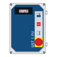
Shelter connection - fig. 20
[option 8 (o8)] with UDL-E1 plug module
Y3-1 = L1 mains voltage for tubular and supercharged motors
Y3-2 = N mains voltage for tubular and supercharged motors
Y3-3 = shelter option
Y3-4 = shelter option
Y3-5 = shelter option
Y3-6 = N supercharged motor
Y3-7 = L1 supercharged motor
Y11-1 = sensor signal (reserve)
Y11-2 = GND sensor (reserve)
Y11-3 = +24V sensor (reserve)
Y11-4 = shelter sensor signal
Y11-5 = GND shelter sensor
Y11-6 = +24V shelter sensor
If option 8 is set on 1, option 9 then appears on the display Sh
(shelter mode).
Now it is possible to set the shelter control functions (ON/OFF).
0 = shelter
1 = logical - the shelter must be enabled for ramp enabling
2 = logical+autostart - The shelter is enabled, the door opens and
follows the ramp enabling!
Connection of 6.3 HV external fuse for docklight or internal /
external TRAFFIC LIGHTS fig. 19
An external 6.3 HV fuse for traffic lights or docklight can be
connected to terminals S4 (J33).
19
Connection - 6.3 HV fuse for
docklight/internal-external traffic
lights
4
5
Tube motor
Fuse
6.3 HV
Horn connection - [option 7 (o7)]
If option (o7) is selected in the PEEP module, in the event of error
the alarm horn trips. It is necessary to switch off the voltage using
the main switch to disable the horn. The alarm horn plug must be
connected to the Y10 socket!
20
1 2 3 4 5 6 7
h
h
UDL-E1 plug module
22
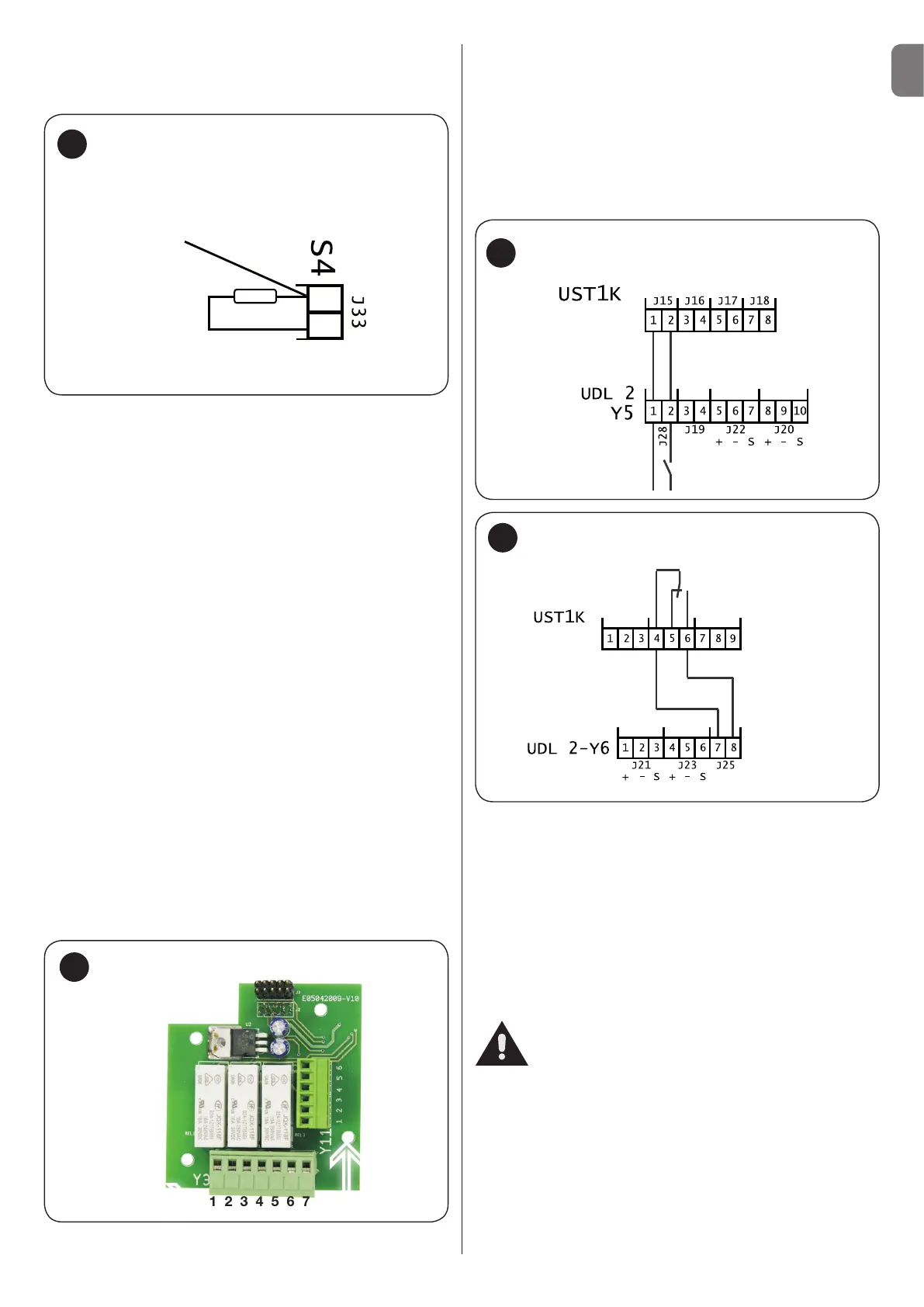
Connection- UST1K door - 1.1 kW
21
X3
Dock enabling
STOP
X4
Door enabling
OPEN IMP CLOSED
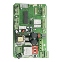
Door connection [option 9 (o9)] - fig. 21-22
If a door with electro-mechanical operation is connected to the ramp
system, the door locking [UDL 2 contact with zero potential] terminal
Y5/1.2 (J28) is to be connected to terminal X3/1.2 of the UST1 and/
or UST1K-1.1kW (STOP terminal X4/1.2 (J15)), while a contact with
zero potential of the K4 module terminal 4.6 (J3) - is connected to
terminals Y6/7.8 (J25 of the UDL 2 (ramp enabling) if you use the
UST1 or UST1K-1.1kW terminal x3/4.6. With these two connections
the door with electric operation and the ramp system are reciprocally
blocked.
Connection of service LED
The service LED connector must be connected to terminal Y11 of
the board.
A service contactor for 1000 cycles is enabled in the memory of
the loading ramp control unit; when the 1000 cycles are reached,
the service LED starts to slowly flash with the loading ramp in
rest position. Contact the assistance service to reset the service
contactor.
Connection of control elements built into the cover
The plug of the control elements must be connected to the Y7
socket!
Attention!
LIMIT SWITCH SETTING door operation
If you use the UDL 2 in conjunction with UST1, UST1K-1.1 kW,
to set the limit switches it is necessary to disconnect the X3/1.2
UST1K1.1 kW connection and replace it with an electrical jumper
(see the instructions described for the limit switch settings)!
Remove the electrical jumper and connect the two wires again
(connection to the UDL 2) when the limit switches are set!
Connection- UST1K door - 1.1 kW