Do you have a question about the Nice WG4024 and is the answer not in the manual?
Crucial instructions and warnings for personal safety during operation and installation.
Inspects each automation component, including sensitive edges, photocells, and the gear motor.
Procedures for putting the automation into operation after all inspection phases are successfully completed.
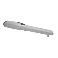
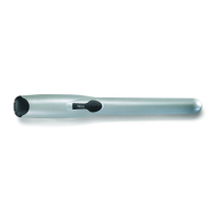
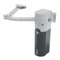
The Wingo4024 is an electromechanical gear motor designed for automating swing gates in a residential context. It operates on a 24V continuous current and features an endless screw reduction gear. The gear motor is powered by an external control unit. In the event of a power outage, the gate leaves can be moved manually by unblocking the gear motor.
The installation process requires careful attention to safety warnings and precautions. It must be performed by a qualified and competent technician in compliance with European legislation, particularly Directive 98/37/CE (Machine Directive) and standards EN 12445, EN 12543, EN 12635, and EN 13214-1.
Before installation, it is crucial to check the gate's suitability for automation, ensuring its mechanical structure is safe and efficient. The gate leaf should move with equal and constant attrition throughout its stroke and remain balanced when stopped manually. The chosen installation surfaces must be solid and guarantee stable fixing. The fixing zone of the gear motor must be compatible with its size, and the rear fixing bracket's position should be calculated using a provided graph to define the maximum opening angle and motor force.
The rear fixing bracket should be sealed to a specific fixing plate and then secured to the wall using dowels, screws, and washers. The front fixing bracket, typically welded directly onto the gate leaf, must be positioned at a different height than the rear bracket, ensuring a distance of 700 mm between the two rotation pins.
The gear motor is then fixed to both the rear and front brackets using screws, washers, and nuts. The nut on the rear bracket should be tightened and then loosened by 1/10 of a turn to allow minimal clearance.
The mechanical limit switch allows setting the stop position of the gate leaf without needing physical stop blocks. To set it, the gear motor is first unblocked, the mechanical stop screw loosened, the gate leaf manually brought to the desired Open position, and then the mechanical stop is brought to the end of the pin and blocked. The same process is followed for the Close position.
Electrical connections involve removing the gear motor lid, slackening the cable clamp, threading the connecting cable, and connecting the three electric wires to the control unit. If the gate opens outwards, the power supply wires must be inverted.
A thorough inspection of the entire system is mandatory to ensure maximum safety and compliance with regulations, particularly EN 12445. This inspection should be performed by expert and qualified staff. It includes checking all components, such as sensitive edges, photocells, and emergency shutdowns, and verifying the gear motor's functionality. This involves unblocking the motor and manually moving the gate leaf to ensure it can be moved with a force no greater than 390N (approx. 40 kg).
The system can only be put into operation after all inspection phases of the gear motor and other devices have been successfully completed. Partial or provisional operation is forbidden.
The automation system provides a high level of safety with detection systems to prevent movement when people or objects are in its range. Children should be prevented from playing near the automation, and remote controls should be kept out of their reach. In case of anomalous behavior, the power should be cut, and the system manually unblocked. Repairs should only be performed by a trusted fitter.
Regular maintenance is essential for consistent safety and maximum lifespan. A programmed maintenance schedule, ideally every 6 months for normal domestic use, is recommended. All maintenance operations must be performed by qualified personnel with the electrical power supply disconnected.
Maintenance tasks include:
The user can periodically clean the photocell glass and remove any obstructions like leaves or stones. Before cleaning, the automation should be unblocked.
The gear motor is equipped with a mechanical system for manual opening and closing during power outages or operating anomalies. This operation should only be performed when the gate leaf is stopped. If an electric lock is present, it must be unlocked first.
To unblock:
To block:
At the end of its life, the product must be dismantled by qualified personnel and disposed of according to local regulations. It contains different types of materials, some recyclable, others requiring specific disposal methods. It is forbidden to dispose of the product with domestic refuse due to potentially polluting or dangerous substances. Users should follow "separated collection" instructions or return the product to the retailer when purchasing a new, equivalent product.
| Brand | Nice |
|---|---|
| Model | WG4024 |
| Category | Gate Opener |
| Language | English |