Digitax ST Installation Guide 35
Issue: 7
Safety Information Introduction Mechanical Installation
Electrical Installation
UL Listing Information
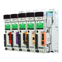
4.8 Encoder connections
Figure 4-9 Encoder
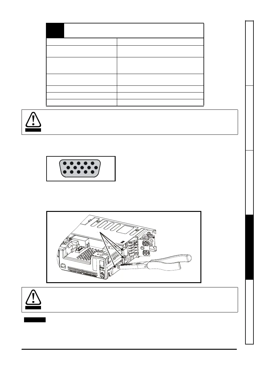
4.8.1 Location of encoder connector
Before using the encoder connectors for the first time, the break-outs need removing as
shown in Figure 4-10.
Figure 4-10 Access to encoder connections
41
Relay contacts
42
Default function
Drive OK indicator
Contact voltage rating
240 Vac, Installation over-voltage category
II
Contact maximum current rating
2 A AC 240 V
4 A DC 30 V resistive load
0.5 A DC 30 V inductive load (L/R = 40 ms)
Contact minimum recommended
rating
12 V 100 mA
Contact type Normally open
Default contact condition Closed when power applied and drive OK
Update period 4 ms
A fuse or other over-current protection should be installed to the relay circuit.
After removing the break-out, ensure that the ground tab is connected to ground (see
Figure 4-11). This will connect 0V of the drive to ground. This is required to enable the
drive to meet IP20 when the break-out is removed.
Do not remove break-out if the connections are not required.
 Loading...


