Do you have a question about the Nidek Medical AR-310A and is the answer not in the manual?
Covers general safety rules for handling and repairing the device.
Highlights safety measures related to the power source and cord usage.
Provides precautions to be taken during maintenance and repair procedures.
Details device classifications regarding electrical shock and water ingress.
Lists technical specifications for various measurement modes.
Troubleshooting steps when the initial screen is not displayed.
Guides on resolving various error codes displayed by the device.
Procedures for troubleshooting non-operational function buttons.
Addresses problems where measurements cannot be performed correctly.
Instructions for removing left, right, front, and rear measuring unit covers.
Procedures for removing the front and rear body covers.
Guides for removing the LCD rear and front covers.
Details on replacing various assemblies like Joystick, Measuring ASSY, and Mire ASSY.
Procedures for replacing main, tracking, driver, base, and interface boards.
Covers replacement of sensors, motors, LEDs, cameras, LCD, and power supplies.
Instructions for replacing shafts, plates, wires, and linear bearings.
Steps to enter the adjustment mode via MENU and CALIB selections.
Guides for attaching various optical adjustment jigs and model eyes.
Procedures for adjusting observation and measurement CCD cameras.
Instructions for adjusting chart position and optical axis.
Steps to perform alignment calibration using the 22-model eye jig.
Detailed procedure for calibrating AR measurements using model eyes.
Steps for KM calibration and checks using specialized jigs.
Procedures for centering and calibrating PD measurement values.
Guide for auto tracking adjustment after motor replacement.
Instructions for rewriting EEPROM data on the driver board.
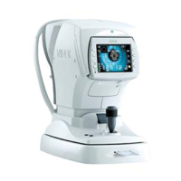
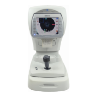
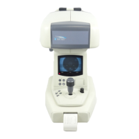
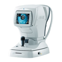
Visual identification of device parts from front and rear views.
Complete and partial wiring diagrams for different device models.
Comprehensive list of error codes, contents, and their detailed explanations.
Detailed parameters for AR-310A/330A, AR-360A, ARK-510A/530A, and ARK-560A.
Catalog of all jigs used for calibration and adjustment procedures.
Cross-reference of electrical/mechanical components and adjustment items.
Visual guide and identification of screws used in device disassembly.
| Brand | Nidek Medical |
|---|---|
| Model | AR-310A |
| Category | Medical Equipment |
| Language | English |