Do you have a question about the Nikon AF-S VR DX Zoom Nikkor 18-200/3.5-5.6G ED and is the answer not in the manual?
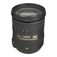
| Focal Length | 18-200mm |
|---|---|
| Maximum Aperture | f/3.5-5.6 |
| Minimum Aperture | f/22-36 |
| Lens Mount | Nikon F |
| Format Compatibility | DX |
| Filter Size | 72mm |
| Angle of View | 76° - 8° |
| Maximum Reproduction Ratio | 1:4.5 |
| Number of Diaphragm Blades | 7 (rounded) |
| Autofocus | Yes |
| Diaphragm Blades | 7 |
| Image Stabilization | Yes |
| Minimum Focus Distance | 0.5m |
| Lens Construction | 16 elements in 12 groups |
| Diameter x Length | 77 x 96.5mm (3.0 x 3.8in) |
| AF Actuator | Silent Wave Motor |
| Optical Design | 16 elements in 12 groups |
| Dimensions | 77 x 96.5mm (3.0 x 3.8in) |
Important safety and procedural notes before starting disassembly.
Specific guidance for handling lead-free solder in product assembly.
Steps for disassembling the 1st lens group and filter ring.
Procedures for removing the 2nd lens group, bayonet mount, and rear cover.
Guide for removing SW unit, Contacts, PCB, and SWM unit.
Procedures for removing the VR unit and aperture blade unit.
Assembling encoder FPC, distance encoder, and fixed tube.
Installing VR unit, aperture, and lens groups.
Assembling 2nd lens group, zoom brush, and cover ring.
Steps for assembling zoom index ring and other final parts.
Required equipment and initial setup for MR encoder inspection.
Detailed steps for inspecting and adjusting MR encoder output.
Checking MR encoder operations and lens-servo stop accuracy.
Inspecting lens-servo time and switch/encoder conditions.
Preparation of optical alignment equipment and tools.
Temporary positioning of lens groups and chart setup.
Detailed steps for rear lens group optical alignment.
Initial setup and mounting procedures for VR adjustment.
Inspecting VR mode switch and adjusting VR lens position.
Procedures for VR gyro and angle difference adjustments.
First-level troubleshooting for VR unit control issues.
Analyzing vibration reduction rate to diagnose VR performance.
Setting up equipment and creating the test chart.
Steps to write aberration compensation data into the lens.