JAA79471-R.3678.A
- A11 ・ AF-S VRDX18-200/3.5-5.6G -
CH1
CH2
④
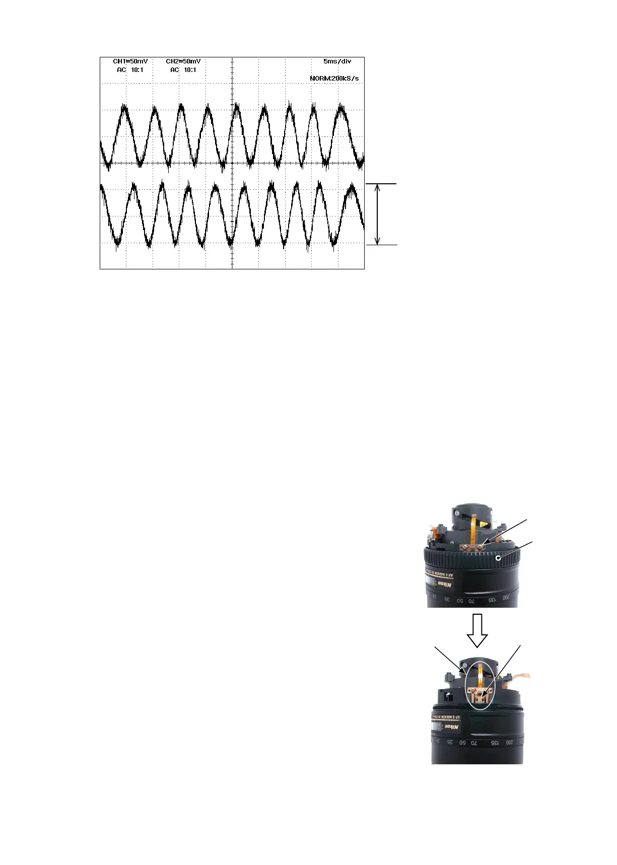
In case the amplitude is small, disassemble up to
the stage of the GMR sensor FPC unit. Then if the
deformation is detected in the MR head, correct the
deform of the MR head. On the other hand, if such
correction is impossible or no deformation is detected,
replace the GMR sensor FPC unit. (Fig.2)
Note: When adjustments are made, prevent the
magnetic surface and MR head from touching the
magnetized driver bit. Otherwise, the magnetic
data may be damaged.
MF ring
#123×2
MR head
GMR sensor FPC unit
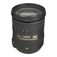
● Oscilloscope setting
V/Div (ch1) : 50 mV
V/Div (ch2) : 50 mV
Coupling : AC
Time/Div : 5 m Sec
Trigger Mode : NORMAL
Trigger Coupling : AC
③
In case large waveform-noise (as shown in Fig. 1) is detected, use the FILTER function.
How to set FILTER function (e.g. DL1540 manufactured by YOKOGAWA
)
1. Press the FILTER button.
2. Select “Smooth” of the menu on screen and turn it ON.
Amplitude
Fig.1
Standard:
Amplitude of all pulses/
waveforms is 80mV or more.
Note:
Check the waveform by moving the
focus ring back and forth from the
innity-end to the close-end positions
entirely.
Fig.2
 Loading...