- 5 -
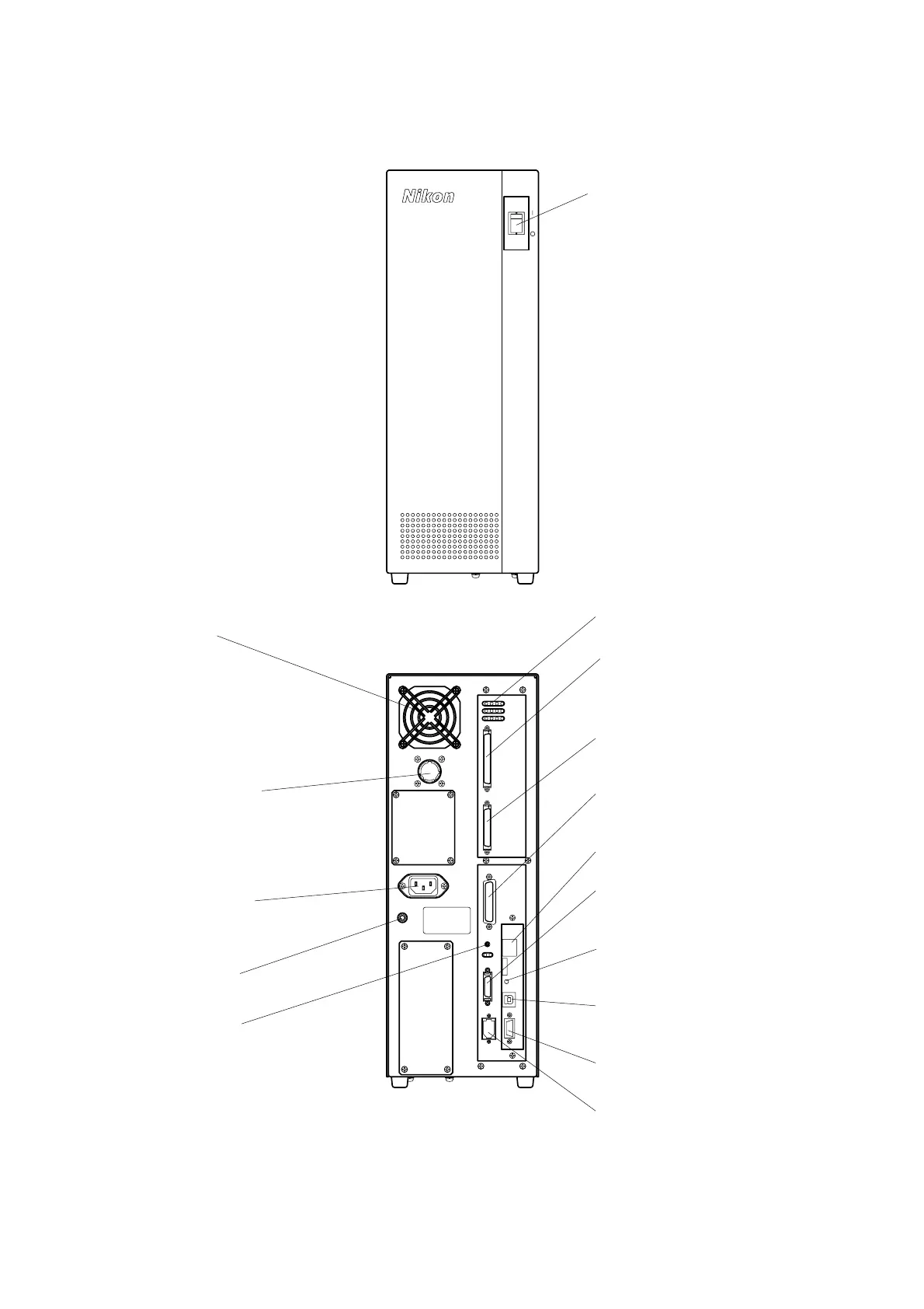
1.5 Controller
CASE
AC IN
MOTOR
PME
HE AD E NC OD ER
J/S
BZ V
D C AMERA IEE E1394
RS-232CUS B(D)Bo o tEth ern et
Power switch
Turns on and off the power
of the main unit.
| : ON
○
: OFF
Status indicator LEDs
Indicate the status of the controller.
Fan motor
HEAD connector
Connect to the HEAD connector on
the main body with the provided
cable.
ENCODER connector
Connect to the ENCODER connector on
the main body with the provided cable.
J/S connector
Connect to the connector on the
oystick unit with the provided cable.
CAMERA connector
Connect the CAMERA cable from
the main body to this connector.
IEEE1394 connector
Connect to the IEEE1394
connector on the host PC with
the provided cable.
USB connector
Connect to the USB connector on
the host PC with the provided cable.
ETHERNET connector
Not used in normal use.
MOTOR connector
Connect to the MOTOR
connector on the main body
with the provided cable.
Power receptacle
Connect to the AC power supply
with the provided cable.
CASE terminal
BOOT ROM switch
This switch is used when writing
firmware.
Buzzer volume
djusts the sound level of the
buzzer.
RS232C connector
Not used in normal use.