36 - FORM NO. 56043088 / Advenger
™
/ BR 600S, 650S, 700S, 800S
SOLUTION SYSTEM
TROUBLESHOOTING GUIDE
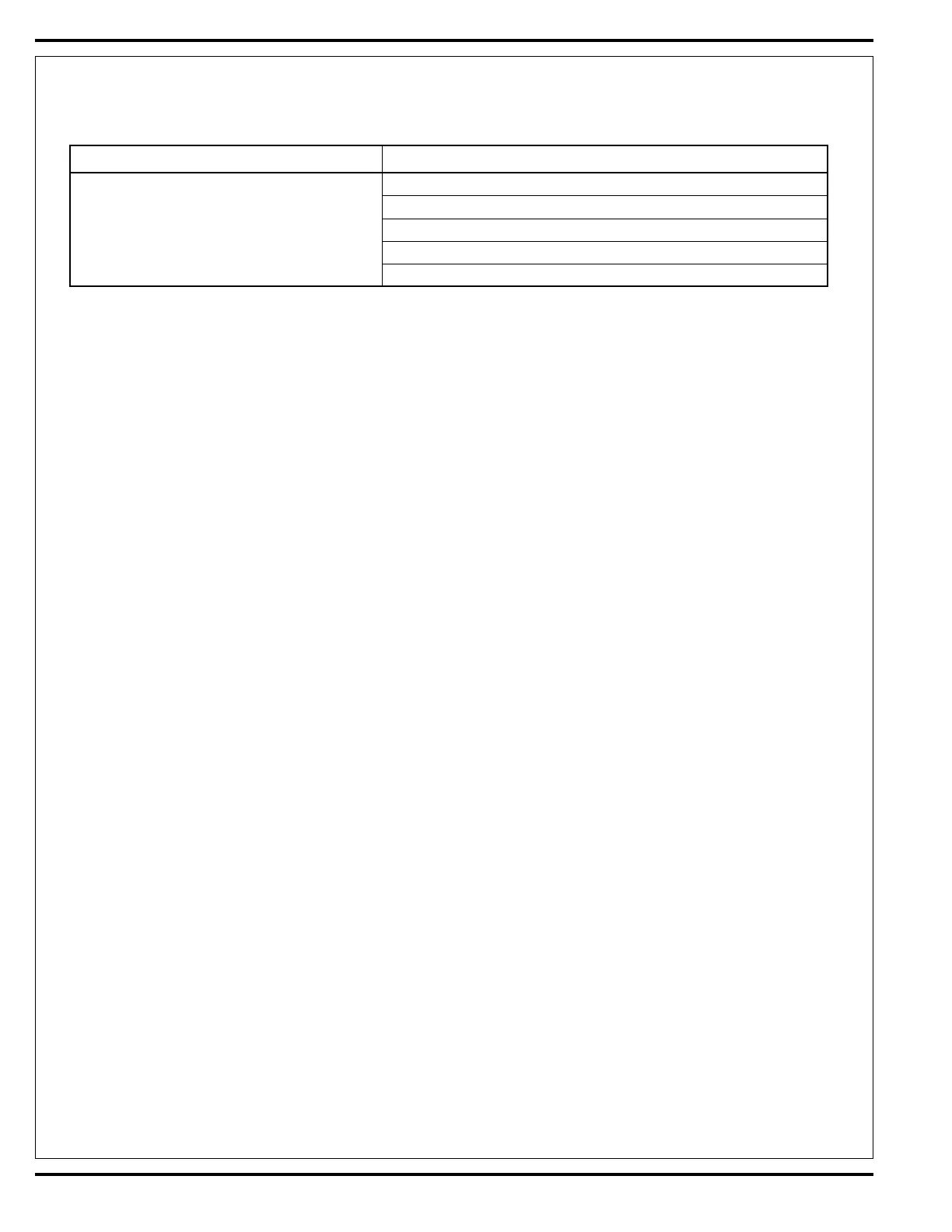
Problem Possible Cause
Inadequate or no solution fl ow No solution in the tank
Main solution fl ow control valve lever is in the off position
Clogged solution fi lter, valves, hoses & solution delivery trough (cyl.)
Defective solution solenoid valve (L1)
Solution system fault in the main controller E1*
*Reference the Main Control Board Troubleshooting Guide in the Electrical System of this manual for further information.
SOLUTION SYSTEM MAINTENANCE
• Solution Tank: See Figure 1. Weekly empty the solution tank; remove the solution Drain Hose (A) from its storage area (located underneath the
left side brush skirt frame). Direct the hose to a designated “Disposal Site” and fl ush the tank with clean water.
• Solution Filter: Remove and clean the inline Solution Filter (B). To access the fi lter housing for removal, work underneath the middle front of
the solution tank (see molded “FILTERØ” callout). No tools are needed to remove the fi lter (hand tighten only). Service Tip: The manual solution
control lever must be placed in the full OFF position. This prevents loss of solution when servicing the fi lter strainer with a partial or full tank.
• Solution Delivery Trough: Note on the cylindrical scrub deck clean the holes in the delivery trough to assure even distribution of solution.
SOLUTION SOLENOID REMOVAL
1 Drain the solution tank or put the Flow Control Valve (C) in the closed position to prevent solution loss.
2 See Figure 3. Locate the solenoid valve, it’s on the right side of the machine under the solution tank. Unplug the L1 solenoid valve wire assembly
connection from the machine harness.
3 Loosen both the inlet and outlet Hose Clamps (D) and (E) that secure the hoses to the valve body.
4 Separate (pry) the solution outlet hose (F) off from its valve body barbed fi tting.
5 Remove the two Hex Screws (G) that secure the valve to the solution tank. Then pull the valve body towards the rear separating it from the
solution inlet Hose (H), completing the part removal.
 Loading...