54 - FORM NO. 56043088 / Advenger
™
/ BR 600S, 650S, 700S, 800S
ELECTRICAL SYSTEM
FUNCTIONAL OVERVIEW OF MAIN CONTROL BOARD
The primary function of the main control board E1 is to position the scrubbing brush(s) with respect to the fl oor surface using a lift actuator motor to
maintain the correct brush pressure and current draw of the brush motor(s). When either the decrease or increase scrub pressure switch is depressed
this will lower the scrub deck to the operating position and by activating the foot pedal start the brush motor. The controller is continuously monitoring
the current to the brush motor and when it senses a current draw out of the desired range it automatically raises or lowers the brush deck by turning
on the brush actuator motor. This process is repeated until the brush motor is shut off. The controller also manages the other supportive systems
such as the squeegee lift, solution on/off, and vacuum motor. Note: See the Know Your Machine system in this manual for a complete explanation
of the machine’s operation.
The secondary function of the main control is to detect any system failures and display an error code on the hour meter display or store it in the main
control board’s recall memory mode. The error code(s) are used to help the serviceperson determine the fault and to quickly guide in repairing a
specifi c system malfunction. Note: See the Troubleshooting Guide for further information.
An additional special feature of the main control board is to change program settings for a set of specifi c machine functions. See the Main Control
Board Special Program Options section in this manual for further information.
TROUBLESHOOTING GUIDE
Any error codes detected by main control board will be displayed on the hour meter LED display as they occur. If more than one-error exists the
display will sequence through the error codes at one-second intervals. The error display will show on the hour meter as the letter E followed by
a two-digit code. EX: E03 would be a drive system fault. When troubleshooting any “Fault Description” noted with a double asterisk (**)
follow the instructions for temporarily disabling the control boards special fault detection program. See the Main Control Board Special
Program Options section in this manual.
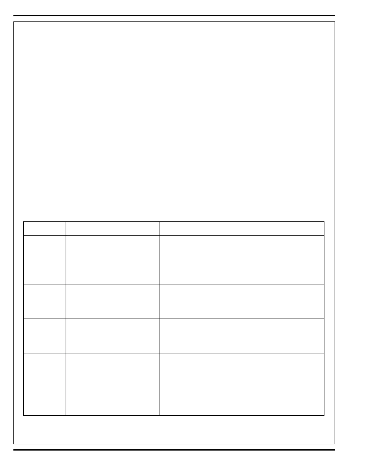
MAIN CONTROLLER ERROR CODES
Error Code Fault Description Troubleshooting Action
E03 Drive system fault 1. Check for a tripped drive motor circuit breaker (45 amp). Investigate
reason for possible mechanical over load. Examples: sticking brakes,
parking brake not released, prolonged ramp climbing. 2. Observe the
green fl ashing wand indicator light (location operator panel) then see
Curtis drive motor controller section to further troubleshoot the drive
system (Table 1).
E04 Scrub deck lift actuator overload 1. Check for binding or frozen brush lift linkage and
normal current load 1 - 2.5 Amps excessive weight on brush deck. 2. Check for short circuit*
max. current load 6 Amps in brush motor and wiring. Repair or replace.
max. current no load 1.4 Amps
E05 Squeegee lift actuator overload 1. Check for binding or frozen squeegee lift linkage and
normal current load 1 - 1.5 Amps excessive weight on squeegee. 2. Check for short circuit* in
max. current load 6 Amps wiring or actuator motor. Repair or replace.
max. current no load 1.4 Amps
E06 Scrub motor overload 1. Check for binding in rotation of brushes or improper brush
Note: See Table #2 Scrub Pressure lift actuator operation. 2. Check the negative supply cable
for detail load current values for the at the brush motor for a wiring problem or improper
different PA#s. modifi cations and also the small YEL/VIO current sense wire. 3. Check
to see that the proper brush programming type is selected*** (disc or
cyl). 4. Check for short circuit* in brush motor or wiring. 5. Inspect
gearbox for failure (disc). Repair or replace. 6. Check excessive belt
tension and idler bearing (cyl.).
*** See the Main Control Board Special Program Options section to activate the Brush Type Selection function.
 Loading...