E
Edward SmithSep 10, 2025
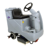
What to do if squeegee lift linkage arm/knob doesn’t raise or lower squeegee on Nilfisk-Advance Floor Machine?
- MMs. Denise LewisSep 10, 2025
If the squeegee lift linkage arm/knob doesn’t raise or lower the squeegee, it could be due to a worn cable bushing under the eyelet of the squeegee cable in the steering column, or a bent/sheared weldment linkage because the squeegee lift cable is too tight. Follow the instructions in the “Squeegee Lift Cable Adjustment - ST” section.