ELECTRICAL SYSTEM 73Service Manual – Advenger, 2800ST, 3800ST, BR 755, BR 855
ELECTRICAL SYSTEM
ACCESS TO PANEL: CHEMICAL PUMP, CHARGER INTERLOCK, FUSES,
CONTACTORS, SPEED CONTROL
WARNING!
1 Open the battery compartment and disengage the red Anderson
battery connectors.
2 Remove the 3 (AXP/EDS - 4) screws fastening the electrical panel
to the front of the machine.
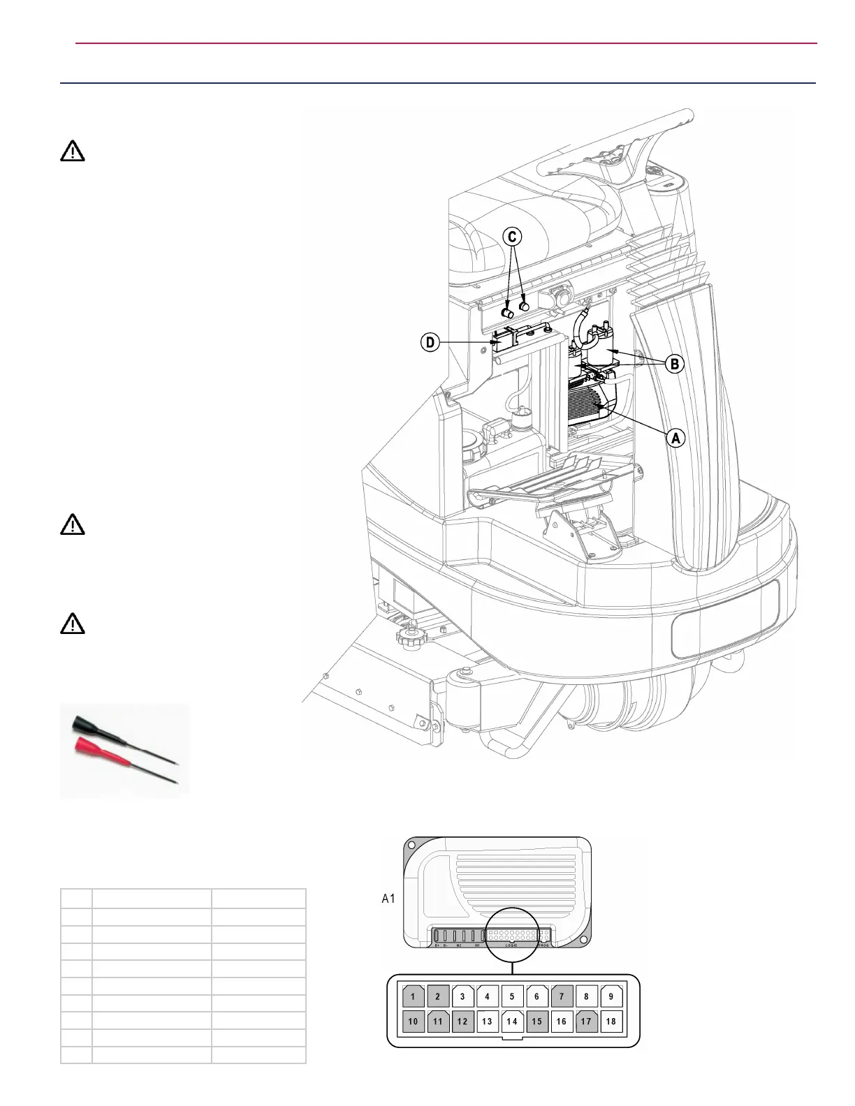
3 See Figure 39. Inside are found the following:
• Curtis speed control (A) with Drive Wheel motor and logic
connections
• K1 and K2 contactors (B)
• Fuses (C) - as shown with onboard charger green interlock wire
connected. If no charger, red wire shown would be connected
there instead.
• Chemical pump (D) (below fuses)
THROTTLE POTENTIOMETER WIPER
MEASUREMENT (NEUTRAL POSITION)
Use a DVM and extended insulated probe tips (shown)
to measure the throttle potentiometer Neutral voltage at
the wiper (pin 4, the GRA wire) referenced to the B-
standoff (green wires).
WARNING!
Open the Electrical Access Panel carefully per step 2
above.
Batteries must be connected to perform this measurement
so extreme caution should be observed.
CAUTION!
Use only insulated test probes designed to
backprobe. SPEED CONTROL IS POWERED
during these tests.
Referenced to the negative battery standoff, the wiper voltage should read:
Neutral: 2 - 3V
Reverse: < 2V (engage pedal in reverse to measure)
Forward: > 3V (engage pedal forward to measure)
Pin Function Wire Color
3 5kOhm Pot High YEL
4 5kOhm Pot Wiper GRA
5 Seat Switch GRA/BLK
6 Brake - RED/WHT
9 Error Status ORN/BLU
13 5kOhm Pot Low VIO
14 Brake + ORN
16 Reverse Alarm BLU/BLK
18 Speed Limit BLK/WHT
FIGURE 39
FIGURE 40

 Loading...