8 - FORM NO. 56041374 / BA 430
ENGLISH
INTRODUCTION
This manual will help you get the most from your Nilfisk BA 430. Read it
thoroughly before operating the machine.
Note: Bold numbers in parentheses indicate an item illustrated on page
2 (Figure A).
This product is intended for commercial use only.
PARTS AND SERVICE
Repairs, when required, should be performed by Nilfisk service personnel
using Nilfisk original replacement parts and accessories.
Call Nilfisk for repair parts or service. Please specify the Model and Serial
Number when discussing your machine.
NAME PLATE
The Model and Serial Number of your machine are shown on the Nameplate
on the machine. This information is needed when ordering repair parts for the
machine. Use the space below to note the Model and Serial Number of your
machine for future reference.
MODEL
SERIAL NUMBER
UNCRATING
When the machine is delivered, carefully inspect the shipping carton and the
machine for damage. If damage is evident, save the shipping carton so that
it can be inspected by the carrier that delivered it. Contact the carrier
immediately to file a freight damage claim.
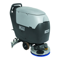
A - KNOW YOUR MACHINE
1 Operator Handle Tube
2 Handle Height Adjustment Knob
3 Squeegee Raise / Lower Handle
4 Battery Tray
5 Brush Raise / Lower Pedal
6 Squeegee Hose
7 Solution Tank Drain Hose
8 Squeegee Assembly
9 Recovery Tank
10 Recovery Tank Drain Hose
11 Solution / Recovery Tank Cover
12 Recovery Tank Automatic Float Shut Off
13 Brush Switch
14 Vacuum Switch
15 Solution Switch
16 Solution Flow Control Lever
17 Battery Connector / Charger Plug
18 Squeegee Mount
19 Battery Condition Indicator
20 Kick Stand
21 Solution Level Indicator
22 Solution Tank
23 Low Voltage Cutout (STD Position)
24 Low Voltage Cutout (MF Position)
PREPARE THE MACHINE FOR USE
B - INSTALLING THE BATTERIES
WARNING!
Use extreme caution when working with batteries. Sulfuric acid
in batteries can cause severe injury if allowed to contact the skin
or eyes. Explosive hydrogen gas is vented from the batteries
through openings in the battery caps. This gas can be ignited
by any electrical arc, spark or flame.
When Servicing Batteries...
* Remove all jewelry
* Do not smoke
* Wear safety glasses
* Work in a well-ventilated area
* Do not allow tools to touch more than one battery terminal at a time
CAUTION!
Electrical components in this machine can be severely dam-
aged if the batteries are not installed and connected properly.
Batteries should be installed by Nilfisk, a qualified electrician, or
the battery manufacturer.
1 Remove the batteries from their shipping crate and carefully inspect
them for cracks or other damage. If damage is evident, contact the
carrier that delivered them or the battery manufacturer to file a damage
claim.
2 Disconnect the Battery Connector / Charger Plug (17).
3 Remove the battery cables from inside the tank. Tip the Solution /
Recovery Tank Cover (11) back until the prop rod catches and then tip
the Recovery Tank (9) forward.
4 Your machine comes from the factory with enough battery cables to
install two 12 volt, 105 amp hour batteries. Carefully lift the batteries
into the battery compartment and arrange them exactly as shown on
page 3 (Figure B).
5 Install the battery terminal covers provided with the machine as shown.
6 Install the battery cables as shown, make sure that the red cable from
the charger plug is connected to the positive terminal and the black
cable connected to the negative terminal. Position the cables so the
battery caps can be easily removed for battery service.
7 Carefully tighten the wing nut on each battery terminal until the terminal
will not turn on the battery post. Do not over-tighten the terminals, or
they will be very difficult to remove for future service.
8 Coat the terminals and posts with grease, petroleum jelly, or spray-on
battery terminal coating (available at most auto parts stores).
9 Connect the Battery Connector / Charger Plug (17).
LOW VOLTAGE CUTOUT SELECTION
Later models of the BA 430 are equipped with a low voltage cutout feature to
prevent over-discharging the batteries. Standard wet cell batteries (flooded
electrolyte) allow for the greatest amount of machine run time due to lower
cutout voltage. If maintenance free batteries (gelled electrolyte) are used, the
low voltage cutout can be set to prevent the over-discharge of the batteries.
The low voltage cutout has two settings, set the first white switch to STD or
position (23) for standard batteries and MF or position (24) for maintenance
free batteries. The selector switch is on the circuit board, which is located
behind the control panel.
 Loading...