12 - FORM NO. 56043094 / Captor
™
4300, 4800, 5400 / CR 1100, 1200, 1400
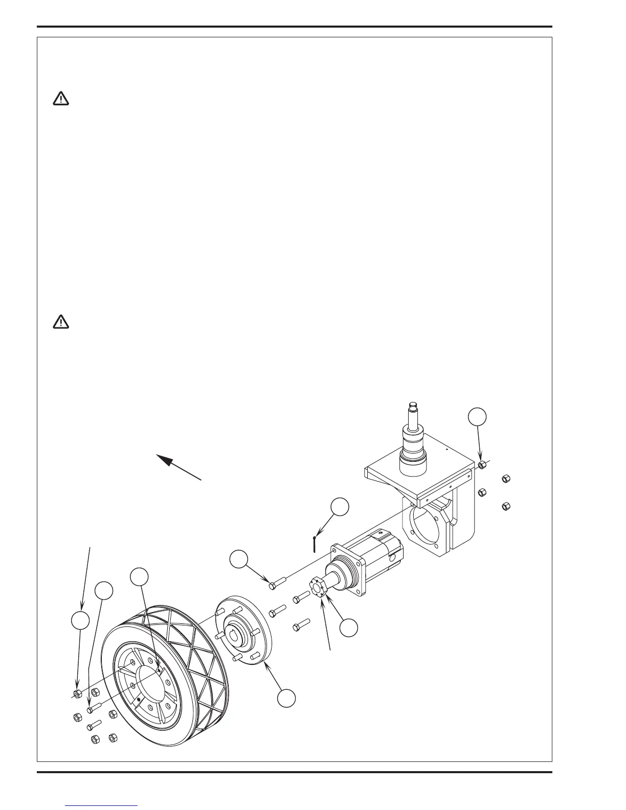
WHEEL DRIVE SYSTEM
D
C
A
B
G
E
F
H
Torque to 375 ft./lbs. (508 Nm) dry
or 475 ft./lbs. (644 Nm) lubed,
then tighten to align cotter pin.
Torque to
100 ft./lbs. (135 Nm).
FRONT
DRIVE TIRE REMOVAL
WARNING!
Never work under a machine without safety block or stands to support machine.
Disconnect battery before servicing.
1 Turn steering wheel to the right full lock position and also remove the squeegee tool.
2 Turn off engine, set parking brake and block front wheels.
3 See Figure 1. Remove the (6) Wheel Lug Nuts (A) (use a 21mm socket). Installation torque is100 ft/lbs. (135 N/M).
4 If removing drive motor, remove the Cotter Pin (B) and loosen the motor shaft Castle Nut (C). Note: You will need a 1-7/16 inch socket for
castle nut (see torque notes Figure 1).
5 Thread (2) 1/2-13 x 2" threaded to HD Pusher Bolts (D) into the (E) Tire Hubs threaded holes.
6 Jack up machine until wheel clears the floor and place jack stands under machine.
7 Turn (thread) in equally both bolts to separate the tire assembly from the wheel motor Drive Hub (F).
WHEEL DRIVE MOTOR REMOVAL
1 Follow steps 1-7 in Drive Tire Removal section.
2 Remove the drive motor shaft castle nut.
3 Mark and remove the three hydraulic hoses at the motor.
CAUTION!
There will be oil in the hoses and motor, be prepared to plug hoses and cap motor fittings.
4 Remove the (4) Hex Screws (G) and Nuts (H) and remove the motor from the spindle weldment. Use a puller to remove the drive hub assembly
from the tapered motor shaft and reuse (salvage).
5 Reassemble in reverse order (see torque notes Figure 1). Operate the machine and check for leaks and proper performance.
FIGURE 1
 Loading...