C397
8
02/2013
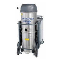
VHT37EXP
US
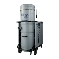
Starting/stopping the vacuum cleaner
Figure 8
WARNING!
Lock the caster brakes (1) before starting the vacuum
cleaner.
Standard version
■ Turn the manual motor starter (2) to the “I” position to
start the vacuum cleaner.
■ Turn the manual motor starter (2) to the “0” position to
turn the vacuum cleaner off.
Checking the rotation direction of the vacuum unit
motor
Check the vacuum cleaner operation by putting a hand over
the inlet.
If the vacuum cleaner does not vacuum any air, the rotation
direction is not correct; remove the plug from the socket and
exchange the connection of two phases inside the plug to
perform the correct phase sequence.
Vacuum cleaner operation
Figure 9
Vacuum gauge (2): green zone (3), red zone (1)
Check the ow rate:
■ when the vacuum cleaner is operating, the pointer of
the vacuum gauge must remain in the green zone (3)
to ensure that the speed of the intake air does not drop
below the safety value of 3937 ft/min (20 m/s);
■ if the pointer is in the red zone (1) it means that the
speed of the air in the vacuum hose is less than 3937
ft/min (20 m/s) and that the vacuum cleaner is not
operating in safety conditions. The lter must be shaken
or replaced.
■ during normal operation conditions, close the vacuum
hose, the pointer of the vacuum gauge must switch from
the green zone (3) to the red zone (1).
WARNING!
When the vacuum cleaner is operating, always check
that the vacuum gauge pointer remains in the green
zone (3).
Consult the “Troubleshooting” chapter if faults occur.
Safety devices
Figure 5
1. Regenerative blower
2. Pressure relief valve
3. Check valve (Clapet)
WARNING!
Do not tamper with the pressure relief valve setting.
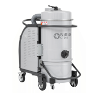
Controls, indicators and connections
Figure 6
1. Container release handle
2. Swivel caster with brake
3. Manual lter shaker knob
4. Vacuum gauge
5. Manual motor starter
6. Band latch
7. Power supply cord
8. Push bar handle
Inspections prior to starting
Figure 7
1. Inlet
Prior to starting, check that:
■ The lter is installed;
■ All latches are tightly locked;
■ The vacuum hose and tools have been correctly tted
into the inlet (1).
■ The polyliner is installed, if applicable.
WARNING!
Do not use the device if the lter is faulty.
 Loading...