6 - FORM NO. 56041342 / SHADOW
™
17/20
J
A
B
D
E
F
G
K
L
M
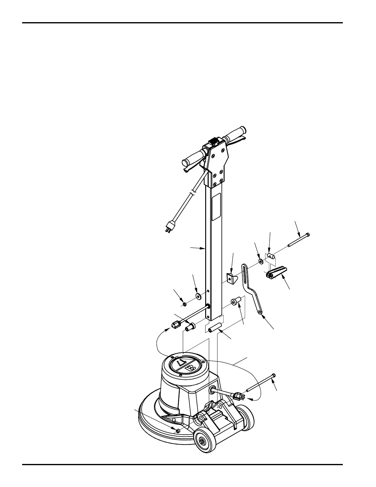
This part "H"
comes assembled
with the base housing.
Plug these (2) power cords together.
K
N
Make sure "foot grip" surface of part
"C"
is facing up as shown.
MACHINE ASSEMBLY
Handle to base, tools needed; (2) 9/16” open end or combination wrenches.
1 Unpack the supplied hardware and become familiar with the part assembly by studying Figure 1.
2 Install the (2) “K” bushings into the base housing support ears as shown.
FIGURE 1
3 Position the Handle Tube “J” between
the “K” Bushings, making sure the power
cord is on the left side of the machine as
shown. Insert the Spacer “N” into the
opening in the bottom of the Handle
Tube “J” and align the spacer with the
holes in the Handle Tube.
4 Attach the handle tube to the base
housing using the long bolt “L” and nut
“M” (hold Spacer “N” in place so Bolt “L”
goes through it).
5 Install the handle arm latch “H” to the
handle tube “J” using the supplied hard-
ware items “A” - “G” as shown.
6 Plug the (2) power cord ends together
as shown.
Items “A” - “G” function together as the handle
position lock lever “Quick-Loc”. The “Quick-
Loc” lever is locked by pushing the lever
down and released by pulling up. NOTE: To
eliminate any slippage, tighten nut “G”.