Vibratory Track Screw Feeder FF/FM503H ver2
49
Brown
(TB1-1)
Blue
(TB1-3)
= CBL-DCIN
CBL-DCIN
2(2/2)
Brown
Blue
= CBL-
SH
NF1
CBL-ACIN
FU2
FU3
CBL-SW(1/2)
SW1
CBL-SW(2/2)
PS1
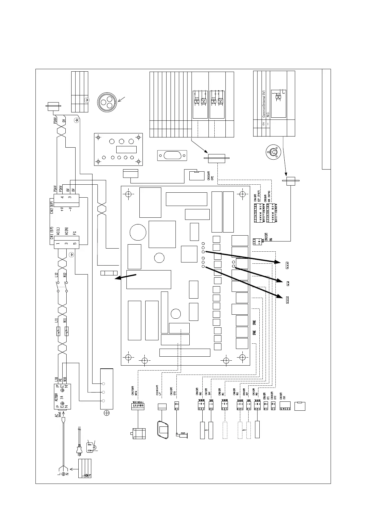
FF/FM503H-MAIN-R Circuit board
FUSE :0215004.MXP(Littelfuse)
AC250V 4A time lug
CN IO (9
P)
CBL-
IO
[Optional]
CASE
PE
Light
5
4
3
2
1
9
8
7
6
1 2 3 4
1 2
1 2 3 4 5 6
CN
SH
(
3P)
BH receptacle 3P socket-contact
AC
B
EMITTER
RECEIVER
FU1
CBL-DISPKEY
FUSE :02181.6MXP
(Littelfuse)
AC250V 1.6A
time lug
OFF
JP4(OPEN)
ON
OFF
JP3(OPEN)
ON
JP5(OPEN)
1
13
14
CN3A
(14P)
2
Power switchFuse
Power supply
D-sub 9P
pin-contact
CN IO Pin layout
(Attention):The input and output circuit and effective/effect-less of
the signal varies in the specifications.
Type
0V
OUT3
OUT2
OUT1
-
IN0
IN1
0V
1
2
3
4
5
6
7
8
9
I/O port
I/O port
SINK
(NPN)
specification
SOURCE
(PNP)
specification
Signal description
0 V DC (External supply)
Take-out Enable(Take out type)
Lack of Screw on Track
Spare
Lack of Screw in Basket [Optional]
N.C.
Screw Feeding(Automatic type)
Operation Enable(Take out type)
24 V DC (External supply)
PIN9
PIN7,8
PIN2,3,4,5
PIN1
PIN7,8
PIN1
PIN9
PIN2,3,4,5
IN :DC24V 10mA (typ.)
OUT:DC24V 40mA (max.)
IN
OUT
IN
OUT
OUT0
Pin No.
Electrical
specifications
of I/O port
CN
SH
Pin layout
DC24V(to SH300)
0V
PE
A
B
C
0V
P24V
Signal description
Pin No.
Type
2
5
FF503H
DISPKEY
Circuit board
Noise filter
(
When viewed from outside.
)
(
When viewed from outside.
)
CBL-DCIN
2(1/2)
IN: AC85-265V
47-63Hz
OUT:DC24V 3.2(3.8)A
PHS1
PRS1
PRS2
M
1
COIL1
SOL1
SPARE(CN14(2P))OT1
SPARE(CN15(2P))OT2
Communication(CN1(5P))232
Stepping motor
(Hopper track)
Vibrator
(
Track
)
Solenoid valve
(Screw feeding)
Photoelectric
sensor
(Chute rail work detect)
Proximity switch
(Basket work detect)
Proximity switch
(Hopper track lower limit)
External
I/O
receptacle
SH300
receptacle
FF
503H
FF
503H
SINK(NPN)
SOURCE(PNP)
EMITTER
RECEIVER
[Optional]
[Optional]
Light
PHS2
Photoelectric
sensor
(Escapement unit work detect)
The AC100V cable with the plug is
Japanese domestic exclusive goods.
Power source(*1)
AC100-240V 50/60Hz 50VA(max
)
Wire color
AC input power cable
Brown
Yellow/Green
Pale blue
(*1)An AC input power cable and a cable to connect
are different corresponding to the specifications.
G
W
PE
(
Yellow/Green
)
Earth
L(
Black
)
Phase/application
N(
White
)
Neutral
FF503H-30P(3m)
FF503H-30AL(3m)/-50AL(5m)
FF503H
Electric circuit diagram(SH300)
(No cover
)
W BK
R BK
(BL BL BL)
CN
10
CN
11
CN
12
U7
U8
U6
JP4
EC2
EC1
IC2
IC1
TB1
DCC1
CN2
CN4
CN5
CN1
CN3
1
1
1
1
1
+
-
CN
13
CN
14
CN
15
CN6
CN7
CN8
CN9
U13
U12 U14
U2
U4
U11
U9
U1 U3 U5
U10
JP3
IC4
EC3
IC6
CN17
FU1
R65
IC3
R64
IC5
1
1
1
CN16
JP
5
LED1
KEY1
KEY3
KEY2
LED5
CN3A
1
LED2
LED3
LED4
Positionong
groove
1
2
5
6
PRG
(CN2(6P))ISP
CN2(6P)
ISP
The external I/O connector is
installation corresponding to the
specifications.
Moreover,a place of a connection is
chosen corresponding to the following
specifications.
CN FEED Pin layout
(
When viewed from outside.
)
(Attention):The timing of screw feeding varies in the setup of the
model.
IN4
-
0V
1
2
3
Screw Feeding(hand driver type)
N.C.
Common(Internal 0V)
I/O port
Type Signal description
PIN1
PIN3
IN :DC24V 10mA (typ.)
IN
DC24V
0V
Electrical
specifications
of I/O port
Pin No.
CBL-FEED
CN FEED (3
P)
3P pin-contact
1
32
FM
503H
Screw feeding
receptacle
(Hand driver type)