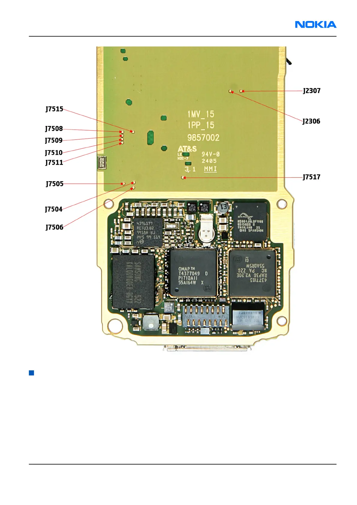
Figure 60 Test points for oscilloscope - top
Receiver troubleshooting
Introduction to Rx troubleshooting
Rx can be tested by making a phone call or in the local mode. For the local mode testing, use Phoenix service
software.
The main Rx troubleshooting measurement is RSSI measurement. This test measures the signal strength of
the received signal. I and Q branches can be measured separately. For GSM RSSI measurement, see GSM Rx
chain activation for manual measurements / GSM RSSI measurement (page 7–10).
In GSM, the input signal can be either a real GSM signal or a CW signal that is 67.771 kHz above the carrier
frequency.
RM-180
RF Troubleshooting and Tuning Guide Nokia Customer Care
Issue 1 COMPANY CONFIDENTIAL Page 7 –9
Copyright © 2006 Nokia. All rights reserved.
 Loading...