MJ-70 module jig concept
Module jig concept is meant for BB / RF testing + tuning and for flashing purposes.
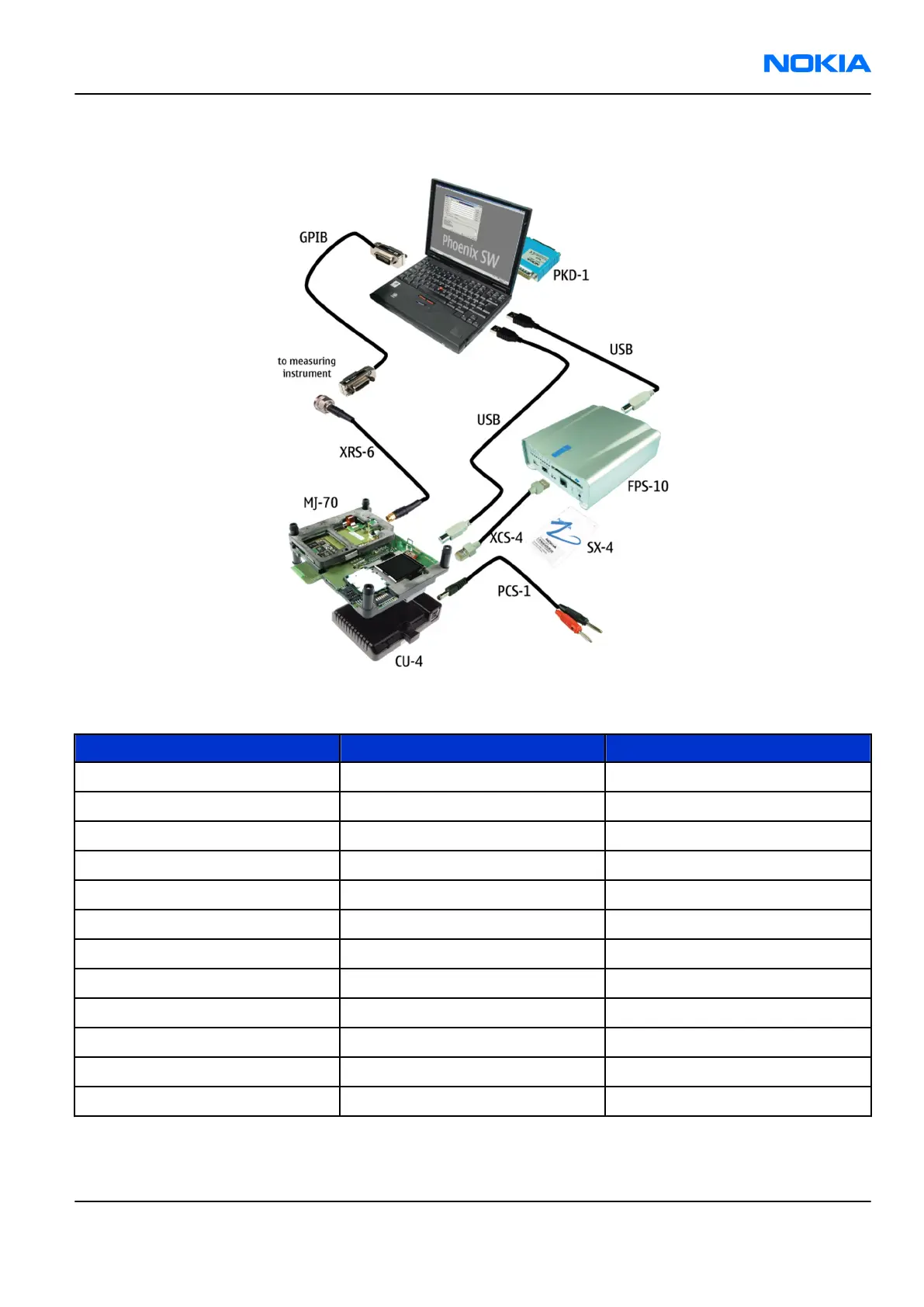
Figure 32 MJ-70 module jig service concept
Item Type Description
1 MJ-70 Module jig
2 CU-4 Control unit
3 FPS-10 Flash prommer box
4 SX-4 Smart card
5 XCS-4 Modular cable
6 PCS-1 DC power cable
7 Standard USB cable
8 Standard USB cable
9 GPIB control cable
10 XRS-6 RF cable
11 PKD-1 SW security device
12 RF shield box
Note: Item 12 not shown in the picture.
RM-180
Service Tools and Service Concepts Nokia Customer Care
Issue 1 COMPANY CONFIDENTIAL Page 4 –15
Copyright © 2006 Nokia. All rights reserved.
 Loading...