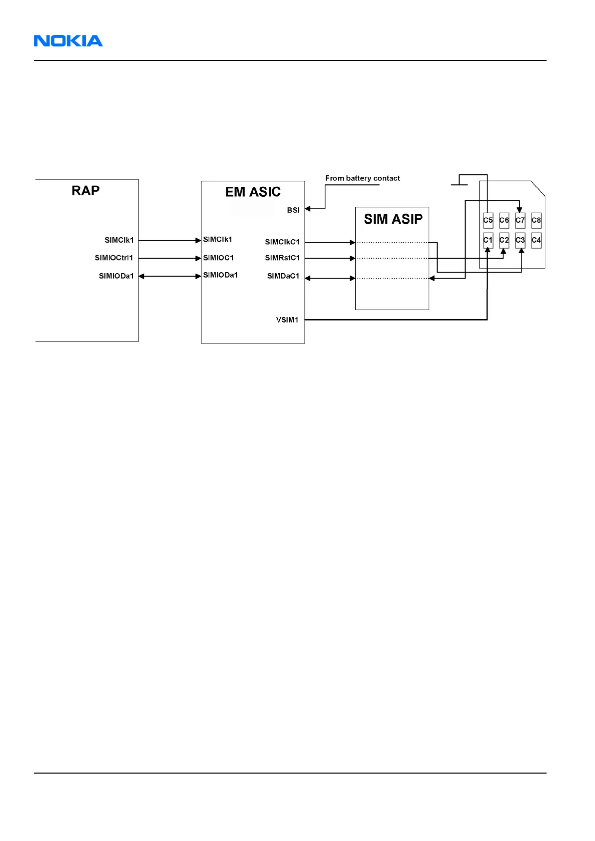
SIM interface
The device has one SIM (Subscriber Identification Module) interface. It is only accessible if battery is removed.
The SIM interface consists of an internal interface between RAP and EM ASIC (N2200), and of an external
interface between N2200 and SIM contacts.
The SIM IF is shown in the following figure:
Figure 91 SIM interface
The EM ASIC handles the detection of the SIM card. The detection method is based in the BSI line. Because of
the location of the SIM card, removing the battery causes a quick power down of the SIM IF.
The EM ASIC SIM1 interface supports both 1.8 V and 3.0 V SIM cards. The SIM interface voltage is first 1.8 V
when the SIM card is inserted, and if the card does not response to the ATR a 3 V interface voltage is used.
RS MMC interface
The reduced size (24 mm x 18 mm x 1.4 mm) multimedia card slot is located under the battery. The device
supports RS MMC hot insertion, which enables to remove/insert the card when the phone is powered on.
The RS MMC card is connected to the application processor MMC/SDIO2 (1.8 V) interface. The MMC interface is
shown in the following figure:
RM-180
Nokia Customer Care System Module
Page 9 –16 COMPANY CONFIDENTIAL Issue 1
Copyright © 2006 Nokia. All rights reserved.
 Loading...