Table 10 SIM interface
Pin Name Parameter Min Typ Max Unit Notes
4 DATA 1.8V Voh 0.9xVSI
M
VSIM V SIM data (output)
1.8V Vol 0 0.15xVSIM
3V Voh 0.9xVSI
M
VSIM
3V Vol 0 0.15xVSIM
1.8V Vih 0.7xVSI
M
VSIM V SIM data (input)
1.8V Vil 0 0.15xVSIM Trise/Tfall max
1us
3V Vil 0.7xVSI
M
VSIM
3V Vil 0 0.15xVSIM
5 NC Not connected
6 GND GND 0 0 V Ground
VSIM specified in regulator section in this document
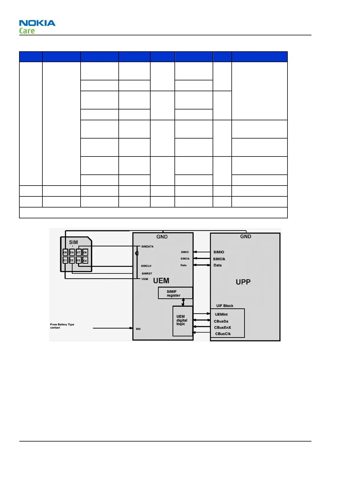
Figure 112 SIM interface block diagram
RM-362; RM-363
System Module
Page 6 –16 COMPANY CONFIDENTIAL Issue 1
Copyright © 2008 Nokia. All rights reserved.