When a wire size is installed which is lar
er than the
minimum size indicated above, the wire must be fused
in accordance with the re
uirements of the R.V.I.A.
A119.2 Standards or local
overnin
codes.
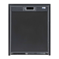
Reversing Door Swing
Your refri
erator is e
uipped with convertible door
hin
es. The hin
in
of the door can be chan
ed to the
opposite side an
time
ou wish.
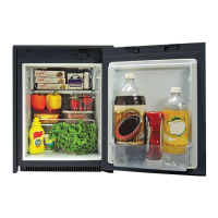
1. Remove all items of food,
uices, etc., from the
door.
2. Usin
a slotted screwdriver, remove the top
hin
e pin.
3. Remove the travel latch b
liftin
out of the door.
4. Remove the door b
openin
sli
htl
and pullin
the top of the door awa
from the refri
erator. Lift
the door up and off the lower hin
e pin.
5. Remove the lower hin
e pin.
6. Usin
a Phillips screwdriver, remove the travel
latch bracket.
7. Remove the bottom hin
e bracket and reposition
to the location where the travel latch bracket was
removed.
8. Remove the top hin
e and reposition at the bot-
tom on the opposite side.
9. Mount the travel latch bracket to the opposite
side from which it was removed.
10. Replace the bottom hin
e pin bracket and relo-
cate the bottom of the door on the hin
e pin and
close door.
11. Replace the top hin
e pin.
12. Replace travel latch in door.
13. Open and close the door several times to insure
proper door seal. Ad
ustments, if needed, can be
accomplished b
loosenin
both hin
e brackets
and repositionin
.
Insulating the Flexible Exhaust Piping
The flexible exhaust pipe must be insulated prior to
installation into the vent terminal housin
. The flexible
exhaust pipe connects to the flue tube of the refri
era-
tors coolin
unit and routes to the bottom openin
of
the vent terminal housin
. Use the non-combustible
insulation material supplied with the vent-air intake/ex-
haust kit.
Do not insulate the Air Intake pipe.
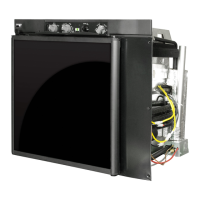
Installing Refrigerator into the Enclosure
Set refri
erator into enclosure and slide it back
enou
h to connect
as suppl
pipin
to manual shut-off
valve located at top of the refri
erator. Connect 12 volt
DC suppl
to terminal block also located at top of
refri
erator. Connect AC power cord to receptacle.
Place the "O" rin
s onto ends of both flexible pipes.
Bend flexible pipes so the
clear top of enclosure
Connect pipin
as follows:
Exhaust Pipe - This pipe is insulated and connects to
the flue tube of the coolin
unit. Route
and connect to the bottom openin
of
the vent terminal housin
.
Intake Pipe - This pipe is
not
insulated and connects
to the burner cover. Route and connect
to the top openin
of the vent terminal
housin
.
Secure both flexible pipes to vent terminal housin
with lockin
washer and screw. Slide refri
erator com-
pletel
into enclosure.
Testing of the Vehicle’s Gas Supply Piping
When installation is complete, the propane
as
suppl
pipin
must be inspected and tested for leaks
from the refri
erator to the main
as suppl
tank. Use
a leak detection solution.
Do not test for leaks with an
open flame.
If compressed air is used for leak testin
, the pressure
must not exceed 1/2 psi
14 inches water column
.
The appliance and its individual shutoff valve must be
disconnected from the
as suppl
pipin
s
stem durin
an
pressure testin
of that s
stem at test pressure in
excess of 1/2 psi
14 inches water column
.
The appliance must be isolated from the
as suppl
pipin
s
stem b
closin
its manual shutoff valve durin
an
pressure testin
of the
as suppl
pipin
s
stem at
test pressure less than or e
ual to 1/2 psi
14 inches
water column
.
Check the
as pressure to the refri
erator without
other
as appliances operatin
. The pressure should
not exceed 11 inches water column. With other appli-
ances operatin
the pressure should not be less than
10.5 inches water column.
Check Out of Flame Failure Safety Device
1. To verif
operation of the flame failure safet
device, start the refri
erator in the
as mode
refer to li
htin
instructions on pa
e 8
and verif
the presence of a flame.
2. Turn off the
as at the manual shut-off valve or
at the main
as suppl
tank.
3. The flame will
o out and within 3 minutes the
flame safet
device will automaticall
close
an
audible click will be heard as this device closes
.
4. Turn the
as on at the manual shut-off valve.
5. Attempt to li
ht the burner b
placin
the mode
selection button to the
as mode.
Do not push in
the safety valve.
6. Without holdin
the safet
valve in, the burner
flame will not re-li
ht. This indicates the flame
failure safet
device is functionin
.
7.
6