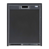
Securing the Refrigerator
The refri
erator can be secured into the enclosure b
screws throu
h the mountin
holes provided at the front
of the refri
erator. This will prevent the refri
erator from
movin
in transit.
Hypot Tests
A Dielectric Stren
th test
H
pot
has been conducted
at the factor
and the refri
erator does not re
uire an
additional test. If H
pot tests are to be conducted on
the 12 volt circuit, the 12 volts must be disconnected
from the refri
erator to protect the flame i
nition circuit.
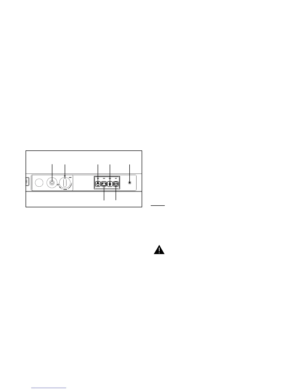
Location of Operating Controls
The refri
erators operatin
controls are located in a
cluster above the refri
erator door.
Description of Controls
(A) Safety Valve
The safet
valve is desi
ned so that an
loss of
flame will stop
as flow to the burner. It is controlled
b
means of a thermocouple that is positioned in the
flame. As lon
as a flame is detected b
thermocou-
ple, the valve will remain open. Upon flame failure,
the valve closes, shuttin
off
as flow to burner.
Durin
as i
nition process, the safet
valve button
must be held in until a flame is established at burner.
(B) Thermostat
The thermostat controls both the
as and the AC
electric operations, thereb
eliminatin
the necessit
of
resettin
each time a different power source is se-
lected. Rotate the thermostat knob clockwise to make
refri
erator cabinet colder.
(C) 120 Volts AC Operation
Pressin
button
C
selects AC mode of operation.
When AC mode is selected and AC volta
e is supplied
to refri
erator, the refri
erator will operate on 120 volts
AC.
(D) 12 Volts DC Operation
Pressin
button
D
selects DC mode of operation.
When DC is selected and DC is available to refri
erator,
the refri
erator will operate at full coolin
power. The
DC operation is a continuous run
no thermostat con-
trol
mode.
(E) Gas Operation
Pressin
button
E
selects Gas mode of operation.
The refri
erator is e
uipped with electronic i
nition.
When
as mode is selected, the electronic i
nition
is ener
ized and sparkin
is
enerated at burner
Note: Push safet
valve button in and hold until
flame is present at burner
. Sparkin
will continue
until a flame is present at burner. When a flame is
sensed b
the electronic i
nition module, the
sparkin
ceases and flame indicator
G
illumi-
nates indicatin
refri
erator is operatin
on
as.
(F) Off
Pressin
button
F
will interrupt all power sources and
cease operation of refri
erator.
Lighting and Start-Up Instructions
The Li
htin
and Start-Up Instructions are located on
the top portion of the interior door liner.
Refer to Fi
ure 5 for location of the operatin
controls.
Notice: When warm humid weather conditions are ob-
served, operate the refrigerator on either AC or
DC electric for a minimum of five (5) minutes
before attempting to follow the Start-Up Instruc-
tions for Gas operation.
Gas Operation
Do not hold gas valve in more than 30 seconds. If the
flame is not indicated within this time, press selector
switch (F), wait 2 minutes, and retry. Continuing to hold
the gas valve in will cause gas to build up in the burner
area and can result in an explosion which can cause
property damage or severe personal injury.
1. Set thermostat
B
to the start settin
.
2. Press mode selector button
E
. I
nition spark
will be present at the burner.
3. Push and hold the safet
valve button
A
until
the indicator lamp
G
lows stead
. Continue
to hold the safet
valve button in for 15 seconds
and then release. The indicator lamp should
remain a stead
low. If the lamp turns off, wait
2 minutes, repeat this step.
A B
C
D
E
F
G
Fi
ure 5
WARNING
7