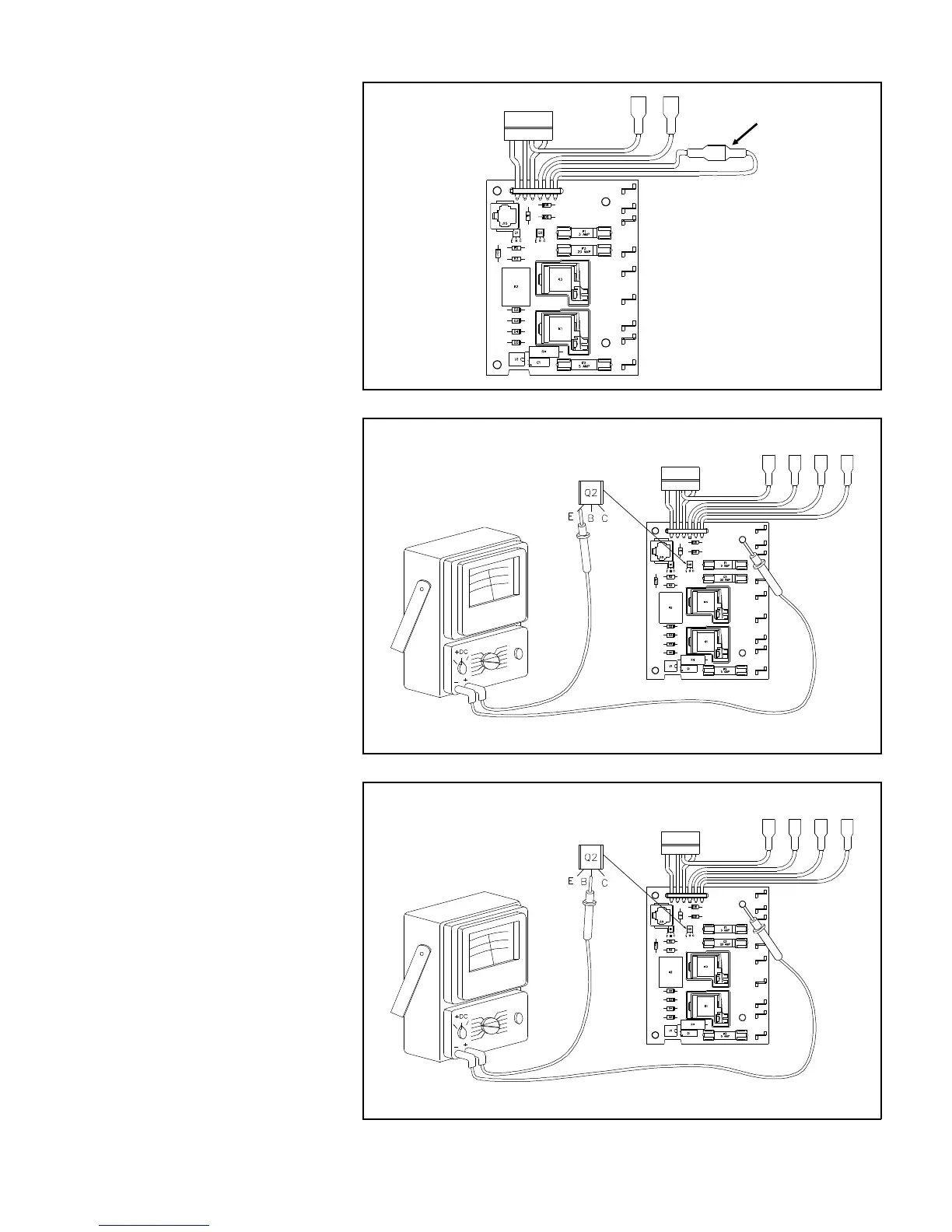
7. For the single door models,
check that the two blue wires
terminals J10 and J12 are con-
nected together as shown by
Figure 11.36.
8. With the volt-ohm-meter set to
measure 11-12 volts DC check
for 12 volts at the emitter of
transistor Q2 as shown in Fig-
ure 11.37. If you do not have
11-12 volts as shown, connect
J10 and J12 together as
shown in Figure 11.36 (2 door
models only).
9. Set the Mode Selector switch to
GAS, the LP light on the Eye-
brow should be illuminated.
10. If the LP light is not illuminated
you must perform more tests
to find the problem.
11. With Mode Selector at GAS
and 12 Volts present at the
emitter of Q2, check for 10
volts DC at the base of transis-
tor Q2 on the Power Supply as
shown by Figure 11.38. If you
do not have 10 volts the Power
Supply is defective and must
be replaced.
J10, J12 Jumper
Connection
Figure 11.36 Single Door Power Supply
Figure 11.37 12 Volt Check at Q2 Emitter
AC and DC power con-
nected but not shown
AC and DC power con-
nected but not shown
AC and DC power con-
nected but not shown
Figure 11.38 12 Volt Check at Q2 Base
40