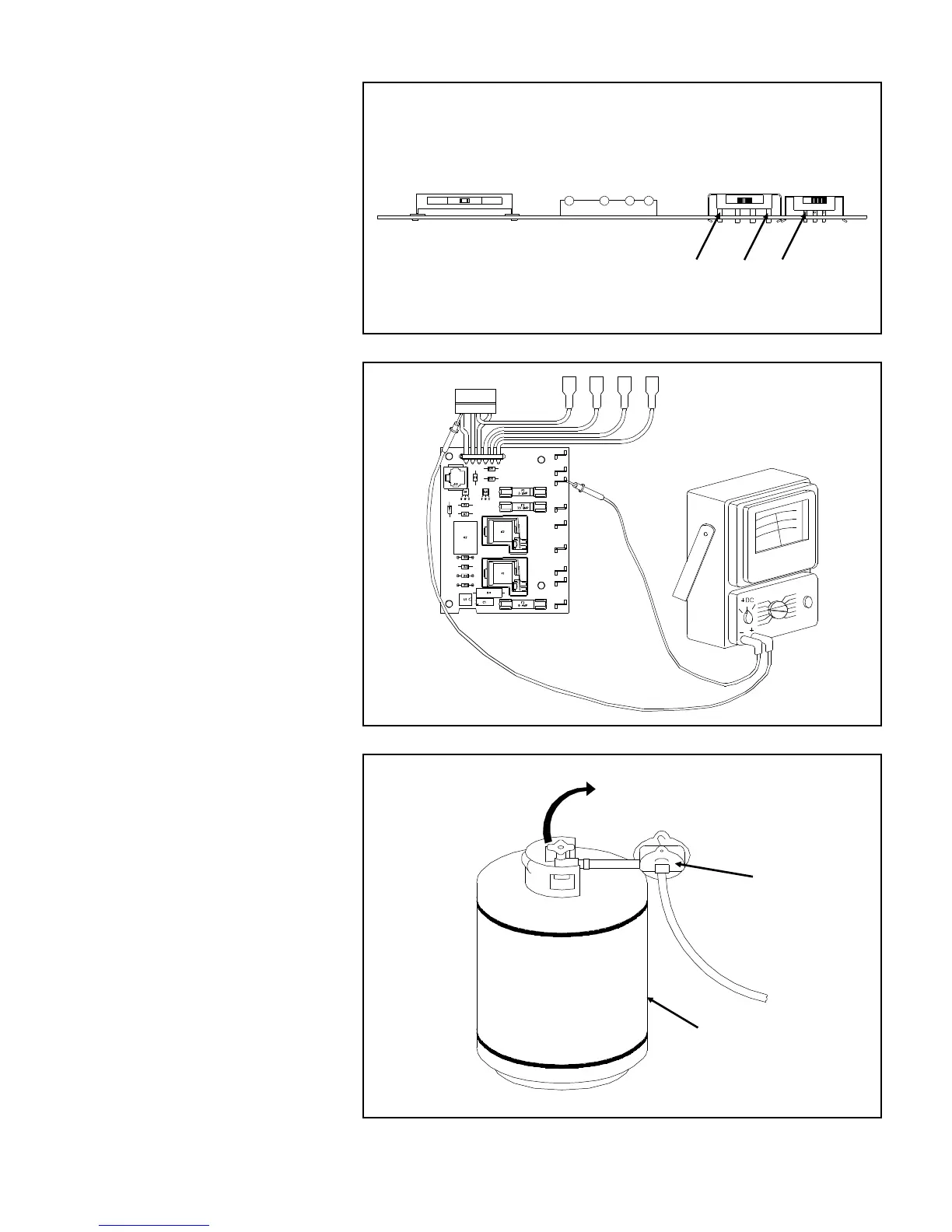
16. With the volt-ohm-meter check
the three points (A, B and C)
indicated in Figure 11.42 for 12
volts DC. If you do not have 12
volts the cable is defective.
A. Set the Mode Selector to all
modes of operation. The 12
volts as indicated in Figure
11.42 should go to zero.
B. If they do not the Eyebrow
board is defective.
17. Set the Mode Selector to GAS.
18. Check for 12 volts DC be-
tween the negative power
supply terminal (J3) and the
left most connection to the
Ignition Module as shown in
Figure 11.43 If you do not
have 12 volts (9.5-15 volts),
replace the Power Supply.
19. Check that the main LP gas is
turned on at the tank as shown
in Figure 11.44
20. Check that the gas pressure is
at 11". See gas pressure infor-
mation in Section 7.
AC and DC power connected
but not shown
Figure 11.43 12 Volt Input Check to Ignition Module
"ON"
Pressure Regulator
LP Gas
Vehicle Main
Tank Supply
Figure 11.44 Main Gas Valve Check
Cable and Thermistor connected
but not shown
A
B
C
Figure 11.42 Control Voltage Check
40