16. With the volt-ohm-meter,
check the points A, B and C in-
dicated in Figure 11.59 for 12
volts DC. If you do not have 12
volts the cable is defective.
17. Set the Mode Selector to all
modes of operation. The 12
volts shown in Figure 11.59
should go to zero volts. If not,
the Eyebrow board is defective.
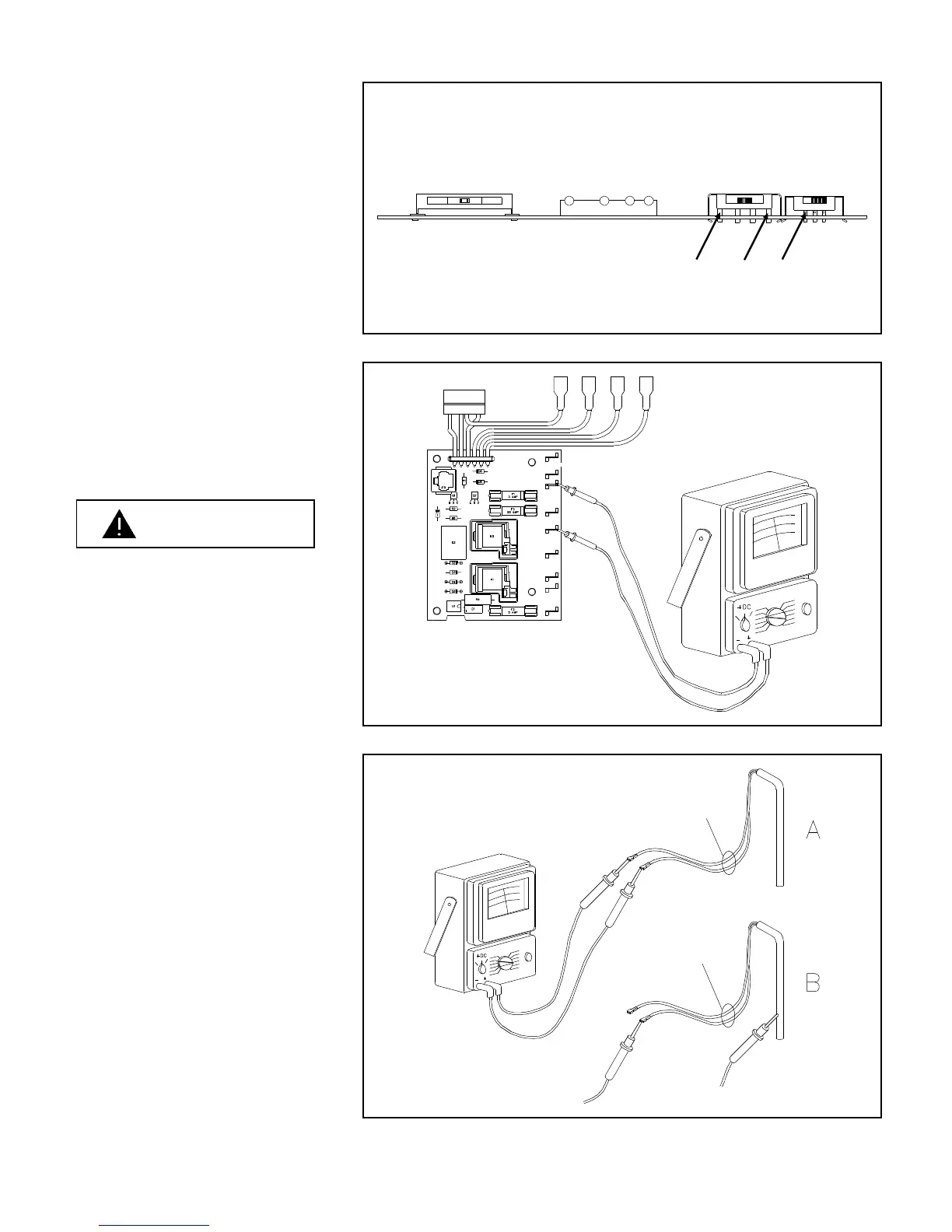
18. Set the Mode Selector to DC.
19. Check the DC heater terminals
J3, J5 on the Power Supply for
12 volts DC per Figure 11.60.
A. If you do not have 12 volts
DC, check the 20 amp fuse.
Replace if blown.
NEVER OVERFUSE A CIRCUIT.
REPLACE BLOWN FUSE WITH
EXACT REPLACEMENT INDI-
CATED BY NORCOLD. OVER-
FUSING OF A CIRCUIT CAN RE-
SULT IN A FIRE.
B. If the fuse is good, replace
the Power Supply.
20. With the volt-ohm-meter set to
the Rx1 scale, check the resis-
tance of the DC heater as
shown in 11.61A. If the resis-
tance is not within allowable
specification (See Technical
Data Section), replace heater.
Next, check the resistance be-
tween each terminal and the
metal heater sheath as shown
in Figure 11.61B. The needle
of the meter should not move
(high resistance). Replace
heater if movement is ob-
served.
A. Set volt-ohm meter to the
Rx10 scale or higher and
check the heater element
for a short to ground. The
meter should show no
movement.
Yellow Leads
AC and DC power connected
but not shown
Figure 11.60 12 Volt DC Heater Output Check
Yellow Leads
Figure 11.61 DC Heater Resistance Check
Cable and Thermistor connected
but not shown
A
B
C
Figure 11.59 Control Voltage Check
WARNING
40