1.5 USS - Data transfer
BU 0050 GB-3111 Subject to technical amendments 39
1.5.4 Parameter range (PKW)
Using the PKW mechanism, parameter processing can be carried out in the cyclical data traffic. For this the
master formulates an order and the inverter formulates the response to this. The parameter area is only used
for transfer with PPO type 1 and PPO type 2.
In principle, the parameter range consists of a parameter identification, in which the type of order (Write,
Read etc.) and the relevant parameters are specified. Individual parameter sets or array elements can be
addressed with the aid of the Index. The parameter value contains the value to be written or read.
Note: A parameter order must be repeated until the inverter responds with the corresponding response
telegram.
If parameter changes are made i.e. parameter identifier values (PKW), care must be taken that
the maximum number of permissible writing cycles to the frequency inverter EEPROM (100,000
cycles) is not exceeded. I.e. continuous cyclical writing must be prevented. For certain
applications it is sufficient if the values are only saved in the RAM memory of the frequency
inverter. For further details se Saving in the EEPROM under Parameter P560 in the frequency
inverter manual.
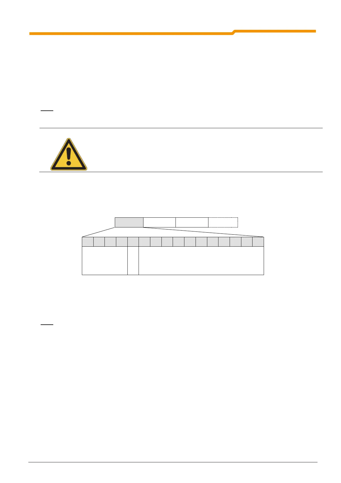
1.5.4.1 Parameter label (PKE)
The order or response and the associated parameters are encrypted in the parameter label (PKE).
The parameter label (PKE) is always a 16 bit value.
PNU: The bits 0 to 10 contain the number of the required parameter (PNU),or the number of the current
parameter in the response parameter from the inverter.
Note: For the inverter parameter numbers (PNU) of the particular inverter series please refer to the
relevant operating instructions for the inverter.
SPM: Bit 11 is the toggle-bit for spontaneous messages. This function is not supported!
AK: Bits 12 to 15 contain the order or response label.
 Loading...


