1.2 USS - Modules
BU 0050 GB-3111 Subject to technical amendments 9
1.2 Modules
1.2.1 SK 500E
1.2.1.1 General
By the use of various modules for display, control and parameterisation, the SK 5xxE can be easily adapted
to various requirements.
Alphanumerical display and operating modules can be used for simple commissioning. For more complex
tasks, various connections to a PC or an automation system can be selected.
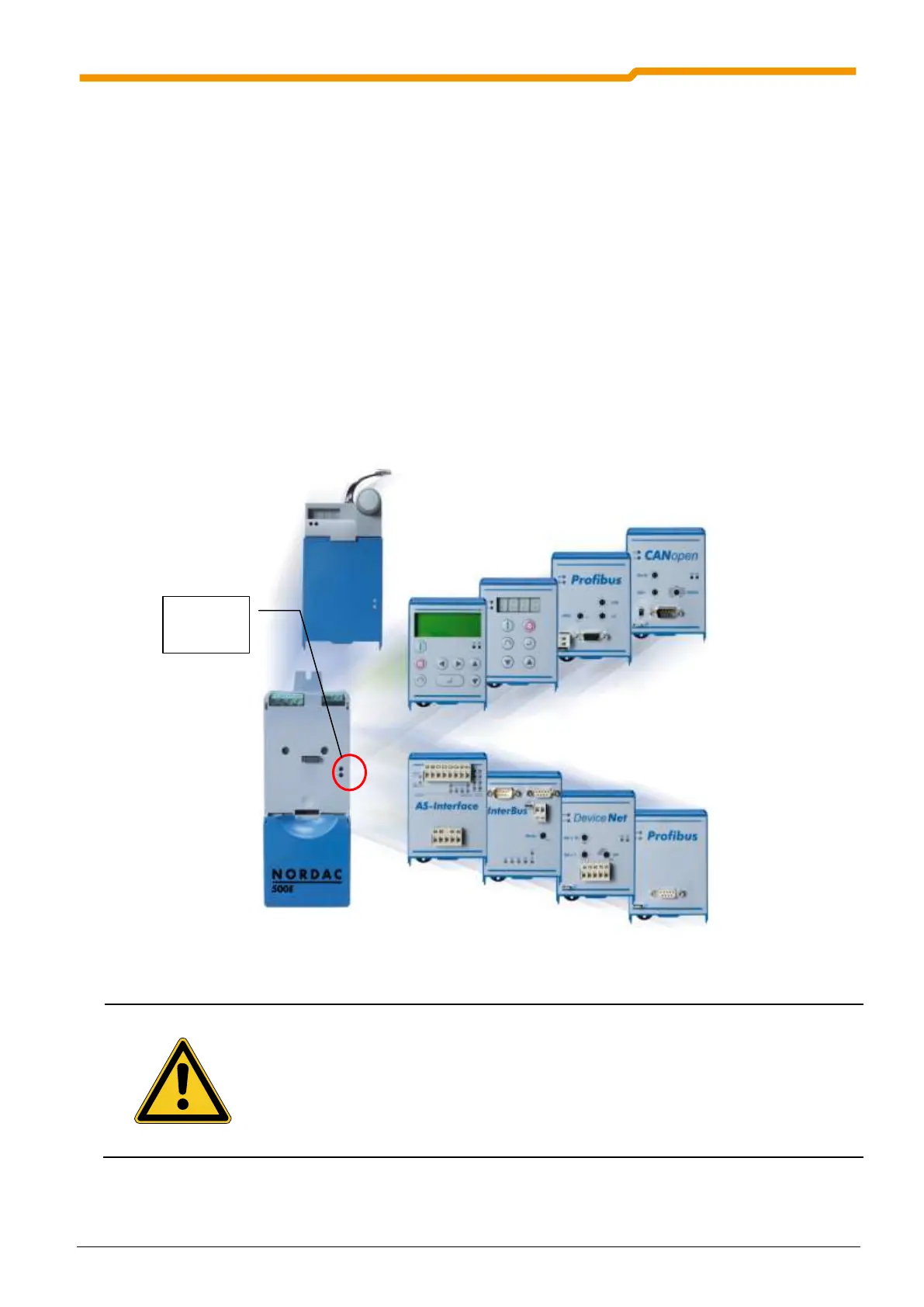
The technology unit (Technology Unit, SK TU3-…) is connected externally to the frequency inverter and is
therefore easy to access and replace at any time.
As delivered, without the technology unit, 2 LEDs (green/red) are visible externally. These indicate the actual
device status.
The green LED indicates that the mains voltage is present and operational, while a flashing code that
increases in speed shows the degree of overload at the frequency inverter output.
The red LED signals actual error by flashing with a frequency which corresponds to the number code of the
error (Manual BU 0500 Section 6).
Modules should not be inserted or removed unless the device is free of voltage. The slots may
only be used for the intended modules.
Installation of a technology unit separate from the frequency inverter is not possible. It must be
connected directly to the frequency inverter.
 Loading...


