Hardware description
GPIO Part Arduino signal
P0.13 Button 1 D2
P0.14 Button 2 D3
P0.15 Button 3 D4
P0.16 Button 4 D5
P0.17 LED 1 D6
P0.18 LED 2 D7
P0.19 LED 3 D8
P0.20 LED 4 D9
Table 4: GPIO connection
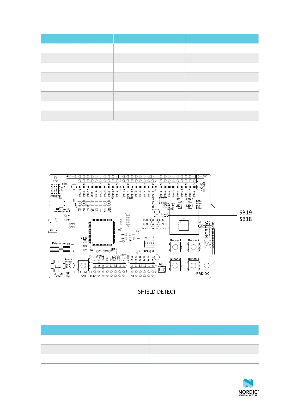
The I/O expander releases these GPIOs for general use when the nRF52 DK is used together with boards
that follows the Arduino standard. The I/O expander can be permanently enabled by shorting solder
bridge SB18, or permanently disabled by cutting the shorting track on SB19. You must also short SB18
when cutting SB19 for full compatibility with the Arduino standard.
The I/O expander can be temporarily enabled by connecting SHIELD DETECT to ground.
Figure 14: Enable or disable I/Os for Arduino standard
In addition to the buttons and LEDs, the following GPIOs are used for the I/O expander:
I/O expander signal GPIO
/INT P0.17
SDA P0.26
SCL P0.27
Table 5: I/O expander connection
4397_500
16