5
Measuring current
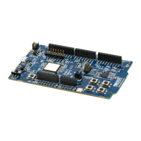
The current drawn by the nRF52832 SoC can be monitored on the nRF52 DK.
Current can be measured using the following test instruments:
• Power analyzer
• Oscilloscope
• Ampere meter
• Power Profiler Kit II (PPK2)
Power analyzer and PPK2 measurements are not described in this document. See the Power Profiler Kit II
User Guide for more information.
For measuring instructions, see Using an oscilloscope for current profile measurement on page 26 and
Using an ampere meter for current measurement on page 27.
Note: When measuring the current consumption:
• It is not recommended to use a USB connector to power the DK during current measurements
due to potential noise from the USB power supply. It is recommended to power the DK from a
coin cell battery or external power supply on connector P21 (1.7–3.6 V).
• The current measurements becomes unreliable when a serial terminal is connected to the
virtual COM port.
• After programming the nRF52832 SoC, the USB must be disconnected and the DK power cycled
to reset the debugger chip before current measurement.
For more information on current measurement, see the tutorial Current measurement guide:
Introduction.
5.1 Preparing the DK
To measure current, you must first prepare the DK.
The suggested configurations split the power domains for the nRF52832 SoC and the rest of the DK, and
bypass protection components in the power supply chain.
4397_500
25