Do you have a question about the Nordic Semiconductor nRF52 and is the answer not in the manual?
Guidance for skilled users, highlighting ESD susceptibility and safe handling procedures.
Information on proper disposal and recycling of electrical products.
Highlights primary capabilities: Bluetooth LE, ANT+, I/O, Debugger, UART, MSD, NFC.
Details on obtaining schematics, PCB layout, bill of materials, and Gerber files.
Functionality of the SW5 reset button for the nRF52832 SoC.
UART interface via virtual serial port for communication.
Drag-and-drop programming feature and troubleshooting for MSD.
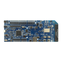
Illustrations of the front and back views of the nRF52 DK PCA10040.
Overview of the nRF52 DK's functional architecture and component interconnections.
Details three power input methods: USB, external supply, and coin cell battery.
Access to GPIOs via connectors P2-P6, P13-P17 for various functions.
Connection of four buttons and four LEDs to dedicated GPIOs.
Manages button/LED conflicts with Arduino shields via an I/O expander.
Optional crystal for enhanced accuracy and low power consumption.
Connecting external debuggers using connector P18.
Methods for programming external boards via P19 (10-pin) or P20 (custom).
Connect external boards using P19 with a standard 10-pin flat cable.
Connect custom boards using the P20 debug output connector.
NFC tag support and antenna input on connector P23.
Overview of solder bridges and test points for functionality control and diagnostics.
Steps to prepare the DK for accurate current measurements.
Capturing current profiles using an oscilloscope and a 10 Ohm resistor.
Measuring average current using an ampere meter connected in series.
Connecting a spectrum analyzer via coaxial connector (J1) for RF signal analysis.
| Max Clock Frequency | 64 MHz |
|---|---|
| Flash Memory | 512 KB |
| RAM | 64 KB |
| GPIO Pins | 32 |
| Operating Voltage | 1.7 V to 3.6 V |
| Temperature Sensor | Yes |
| Operating Temperature | -40°C to +85°C |
| Package | QFN48 |
| Wireless Protocols | Bluetooth 5, ANT |
| ADC | 12-bit, 8 channels |
| UART | 1x |
| Architecture | 32-bit Arm Cortex-M4F |