Hardware description
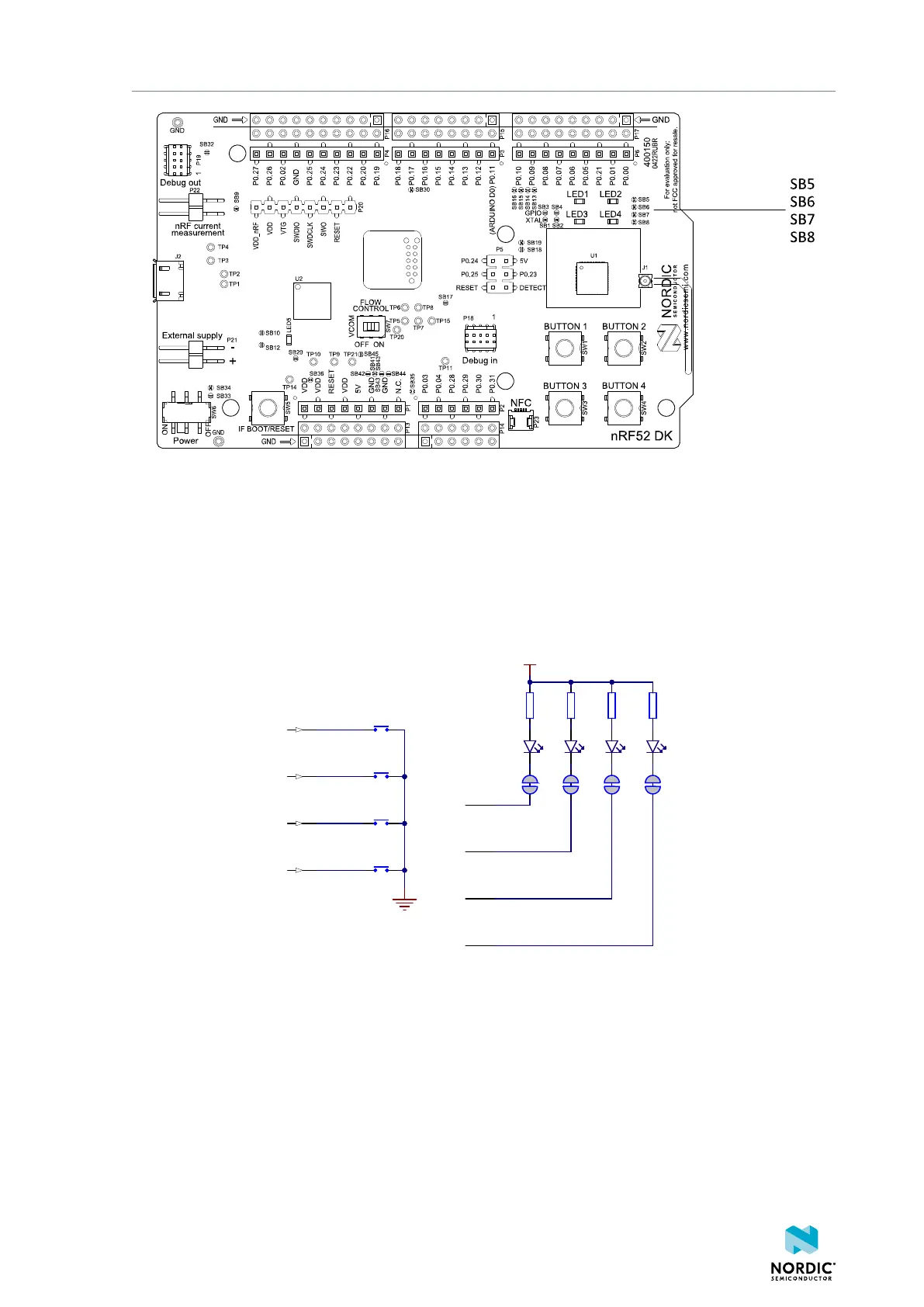
Figure 12: Disconnecting the LEDs
The LEDs and buttons can also be disconnected by using the I/O expander as described in I/O expander for
buttons and LEDs on page 17.
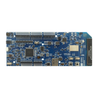
The buttons are active low, which means that input is connected to ground when the button is activated.
The buttons do not have an external pull-up resistor, so the P0.13—P0.16 pins must be configured as
input with an internal pull-up resistor to use the buttons.
The LEDs are active low, meaning that writing a logical zero (0) to the output pin illuminates the LED.
R2
220R
R1
220R
SB6
VDD
R3
220R
SB7
R4
220R
SB8SB5
LED1'
LED2'
LED3'
LED4'
LED1
LED2
LED3
LED4
BUTTON1'
BUTTON2'
BUTTON3'
BUTTON4'
SW1
SW2
SW3
SW4
4
8
12
16
Figure 13: Button and LED configuration
4.5.1 I/O expander for buttons and LEDs
The onboard GPIOs for the buttons and LEDs can conflict with boards that follow the Arduino standard. To
avoid such conflicts, the nRF52 DK has an I/O expander.
4397_500
17