Measuring current
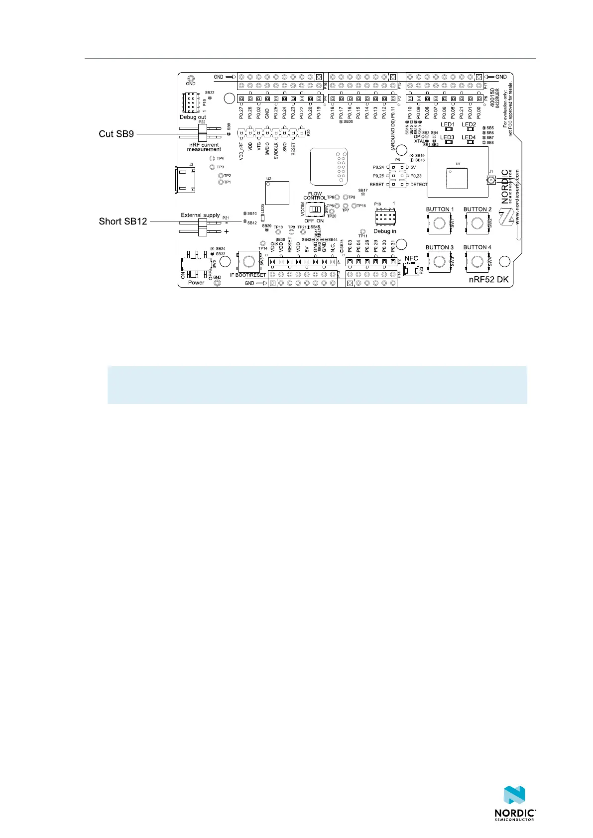
Figure 26: Preparing the DK for current measurements
• To put P22 in series with the load, cut the PCB track shorting solder bridge SB9.
• If using an external power supply, short solder bridge SB12 to bypass the protection diode, which
would otherwise give a voltage drop.
Note: While SB12 is shorted, the DK must not be powered from the USB if there is an external
supply connected because the protection diode has been bypassed.
• To restore normal DK function after measurement:
1. Solder SB9 or apply a jumper on P22.
2. Cut or desolder SB12 to reconnect the protection diode.
• To reprogram the nRF52832 SoC while the DK is prepared for current measurement, disconnect
external supply, ensure there is no battery inserted, remove measurement devices from P22, add a
jumper to P22, and then connect the USB cable.
5.2 Using an oscilloscope for current profile
measurement
An oscilloscope can be used to measure both the average current over a given time interval and capture
the current profile.
Make sure you have prepared the DK as described in Preparing the DK on page 30.
1. Mount a 10 Ω resistor on the footprint for R6.
2. Connect an oscilloscope in differential mode or similar with two probes on the pins of the P22
connector as shown in the following figure.
3. Calculate or plot the instantaneous current from the voltage drop across the 10 Ω resistor by taking
the difference of the voltages measured on the two probes. The voltage drop is proportional to the
current. The 10 Ω resistor causes a 10 mV drop for each 1 mA drawn by the circuit being measured.
The plotted voltage drop can be used to calculate the current at a given point in time. The current can
then be averaged or integrated to analyze current and energy consumption over a period.
4397_500
31